Phone: 252.522.3031 • Fax: 252.522.0214
www.fieldcontrols.com
© Field Controls, LLC P/N 780107600 Rev B 05/23
This manual may be downloaded and printed from the Field Controls website (www. eldcontrols.com)
This manual may be downloaded and printed from the Field Controls website (www. eldcontrols.com)
WARRANTY
For warranty information about this or any Field Controls product, visit:
For warranty information about this or any Field Controls product, visit:
www. eldcontrols.com
Field Controls Technical Support
Field Controls Technical Support
1.800.742.8368
eldtec@ eldcontrols.com
eldtec@ eldcontrols.com
MAINTENANCE
1. Inspect the system annually to ensure proper operation by observing that the fan activates when a call for
heat occurs and deactivates when the call for heat is satis ed.
2. Disconnect power to the CAS-34U unit and repeat Step 1. Note: The unit should not run and the appliance
should not re in this condition.
3. Inspect the duct pipe for cracks and that it is secure to the CAS-34U unit and intake airhood. The CAS-
34U unit will not allow the appliance(s) to re if there is inadequate air ow into the inlet of the CAS-34U.
4. Clear any obstructions, if present, from the inlet of the intake air hood and the outlet of the CAS-34U unit.
5. Periodically, the fan blade chamber may need cleaning. First, disconnect the power supply to the CAS-34U.
Next, disconnect the duct pipe from the unit. Then remove the top pan and clean the fan housing area as
needed. Reattach the top pan, reconnect the duct pipe and the power supply.
TROUBLESHOOTING
1. Burner does not re when thermostat calls for heat.
a. Make sure draft tube is securely fastened to the air pressure switch and is not blocked.
b. Check for continuity across pressure switch terminals when system is operating.
c. Check wiring connections between air pressure switch and appliance.
2. System does not activate when thermostat calls for heat.
a. Check to see if relay closes when thermostat calls for heat.
b. Check wiring connections.
c. Check motor for unrestricted shaft rotation.
3. Exhaust gas odor.
a. Check system draft level during operation.
b. Check vent system on appliance.
c. Check for negative pressure in building.
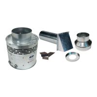
REPLACEMENT PARTS
MODEL DESCRIPTION PART NO.
CAS-34U
PCB Control Assy, CAS-34U
602400200
Motor Assy, CAS-34U
602400300
IAH-4 Intake Air Hood
46292000
IAH-6 Intake Air Hood
46293000
Pressure Switch , CAS-34U
602400400
 Loading...