page 3 of 16
WIRING INSTRUCTIONS
Wire the venter motor and controls in accordance with the National Electrical Code, manufacturer's
recommendations and/or applicable local codes. UNIT MUST BE GROUNDED. Check ground circuit to make
certain that the unit has been properly grounded. The wiring should be protected by an over current circuit
device rated at 15 amperes. Caution must be taken to ensure that the wiring does not come into contact with
any heat source. All line voltage and safety control circuits between the venter and the appliance MUST be
wired in accordance with the National Electrical Code for Class I wiring or equivalent methods.
Route the venter motor and control wiring with an appropriate wiring method. (Diagrams A through H)
NOTE: Control is factory set for 120V wiring. For 24V wiring connect the yellow mode wire to the
24V terminal.
NOTE: Circuit board is polarity sensitive. Follow check-out procedures.
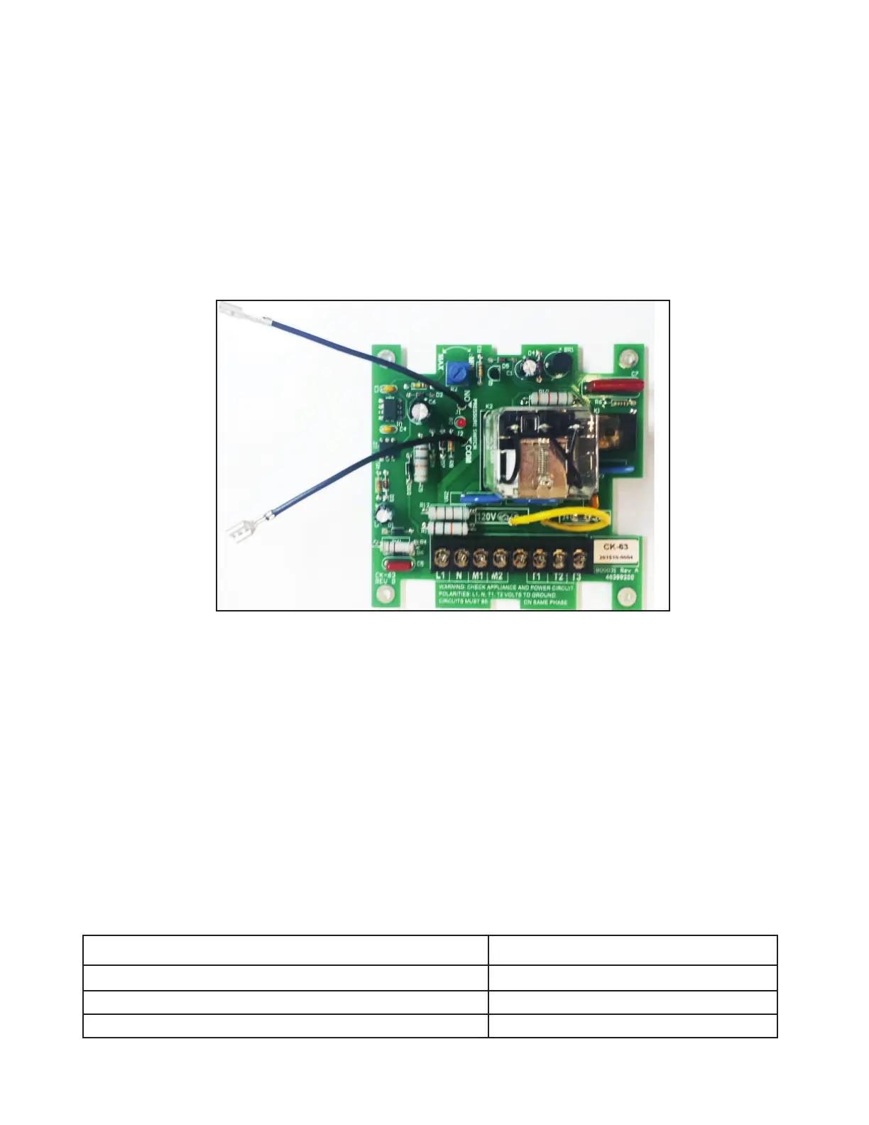
Figure 6- Close-Up of Interior Board Layout
ELECTRICAL RATINGS
Appliance is rated for 120VAC only.
L1: 120VAC, 60Hz, 15A MAXIMUM (supply to M1 and M2)
N: Neutral
M1: 120VAC switched output, 1/3hp maximum load, 7.2 FLA
M2: 120VAC switched output, 1/3hp maximum load, 7.2 FLA
120VAC CONTROL 24VAC CONTROL
T1 120VAC Control Input (supply to T3) T1 24VAC Control Input (supply to T3)
T2 Neutral T2 Common
T3 120VAC switched output 1/8hp (3.8 FLA) maximum load T3 24VAC switched output
P/N 46400900 Rev P 08/19
If Replacing CK-61: All external wiring is the same. Wires connected to the L1, N, M1, T1, T2, & T3 terminals of the
CK-61 will connect to the same terminals of the CK-63.
If Replacing CK-62: All external wiring is the same. Wires connected to the L1, N, M1, T1, T2, & T3 terminals of the
CK-62 will connect to the same terminals of the CK-63. The PPC-4 is no longer needed with a CK-63 and can be
removed from any circuits it was previously installed in.
 Loading...