Doc. 8.8503.00.9
Rev. April, 2018
The following procedure must only be performed by a Fike qualified Service Engineer, who has been assigned to
prepare and complete the de-commissioning of the above referenced Explosion Protection System.
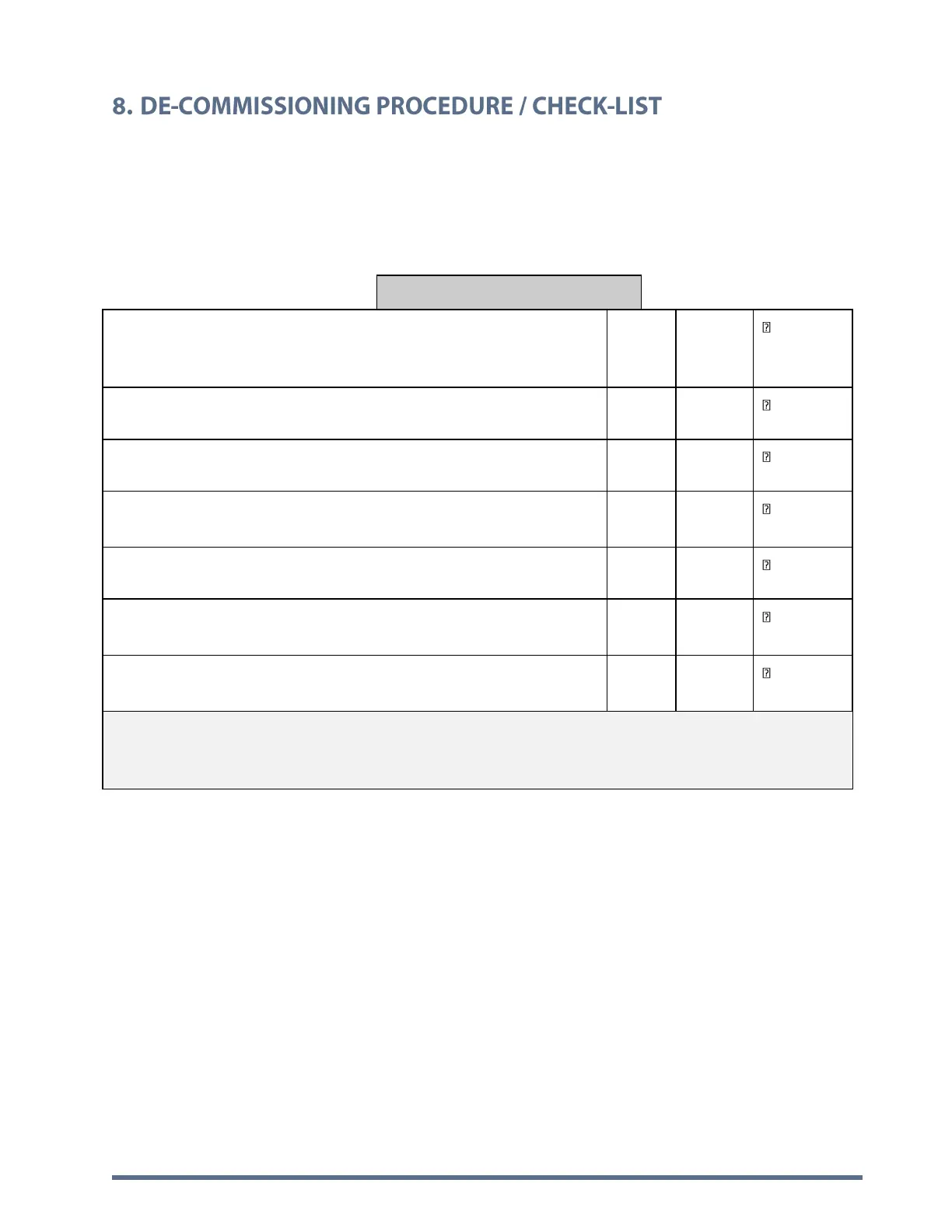
Each step in the listed procedure must be adhered to and completion/acceptance of this form is mandatory. The
Service Engineer must check off each of the following steps. In the case of non-compliance, the observed discrepancy
must be corrected before completion of the system de-commissioning.
1. Use Fike system/project component location diagram to record and
verify the locations of all Fike system components for each zone and
system.
2. Control Panel to be Disarmed/Shutdown.
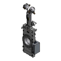
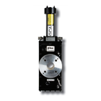
3. All Suppressor/Valve actuators to be shunted.
4. Power supply to the Control Panel to be Isolated by the Customer
and disconnected to prevent accidental reconnection. Fike to Verify.
5. Control Panel battery to be disconnected and removed for disposal.
6. Each actuator is to be removed and placed in a storage boss, to be
either stored on site or removed for disposal.
7. Verify that all Suppressor/valve gauges are reading zero, replace fill
valve cap loosely
ATTENTION: SYSTEM IS NOW DE-COMMISSIONED AND READY FOR
DISMOUNTING BY THE CUSTOMER/OWNER.
 Loading...