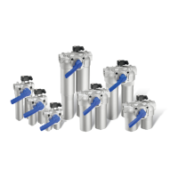
This document describes the Facet HCS Series (End Opening) Horizontal Coalescer Separators, designed for fixed installations and compliant with EI 1581, 6th Edition, Category C, Type S.
Function Description
Facet two-stage coalescer separators are a primary defense against fuel contamination by water and dirt, continuously removing solids and water contaminants from aviation fuels. These units contain both first-stage coalescer and second-stage separator cartridges, operating without internal moving parts. Product is pumped under pressure through the housing inlet chamber and inside/out through multi-media coalescer cartridges. These cartridges trap solid particles (to less than one micron) and cause small water droplets to commingle and grow into heavier, larger drops that fall by gravity to the housing sump area. The cleaned fuel then flows outside/in through second-stage separator cartridges, which strip any remaining water droplets, allowing only clean, dry fuel to pass.
Important Technical Specifications
The Facet HCS-222-1324 model has the following specifications:
- Design Pressure: 150 psi @ 250 °F (10.3 bar @ 121 °C). Other design pressures are available on request.
- Hydrostatic Test Pressure: 195 PSI.
- Maximum Flow Rate (Rated Flow): 104 GPM.
- Maximum Operating Pressure: 150 PSI.
- Maximum DP Across Deck Plate: 75 PSI.
- Sump Volume: 3.2 U.S. Gallons.
- Operational Temperature Range: -20°F / 250°F.
- Vessel Lid Gasket Material: Buna-N.
- Vessel Lid Gasket Part Number: 607731.
- Torque for Vessel Lid Nuts: 60 ft.-lbs.
- Construction: Welded carbon steel (other materials available), ASME Code, Section VIII construction (stamped and certified).
- Interior Coating: Epoxy coated (EI 1541).
- Exterior Coating: Prime coated.
- Closures: Swing bolt head closures, hinged end opening cover.
- Connections: Flanged inlet and outlet connections, 4" inlet/outlet cleanout/inspection connections (when permitted by design).
- Seals: Buna-N o-ring closure seal, knife edge cartridge mounting seals.
- Cartridge Mounting: Choice of rod or screw base coalescer cartridge mounting styles.
- Compliance: Fully complies with EI 1581, Category C, Type S requirements for commercial aviation fuel, suitable for filtration points where significant levels of water and dirt are expected.
Recommended Spare Parts (for HCS-222-1324)
- Coalescer Element: CAA22-5SB (Quantity: 2)
- Separator Element: SS324FA-5 (Quantity: 1)
- Head Gasket: O-RING BUNA-N (Part No. 609919, Quantity: 1)
- Sump Gasket: O-RING BUNA-N (Part No. 694962, Quantity: 1)
Usage Features
- Ease of Servicing: Housings are designed for easy servicing and low maintenance.
- Installation: Available in vertical and horizontal housing designs with a wide selection of coalescer and separator cartridges to meet specific applications. Many standard and optional accessories and connections are available to facilitate piping and installation.
- Pre-Operation Test: After installation, the unit undergoes a fluid test. This involves closing drain valves, opening vent valves/plugs, opening liquid level gauge valves, and slowly opening blocking valves in the inlet and outlet piping to fill the unit. Leaks are checked, and connections are tightened as necessary.
- Operation: To place the unit on-stream, drain valves are closed, liquid level gauge valves are opened, and vent valves/plugs are opened. The system pump is started, and blocking valves are slowly opened to fill and vent the unit. Once filled and vented, inlet and outlet valves are fully opened, and flow rate is checked against the rated flow.
- Differential Pressure Gauge: If purchased, this gauge helps determine when filter elements need replacement. Elements must be replaced when the differential pressure across the filter-separator reaches 15 psi, or at least once per year, whichever comes first.
- Safety Precautions:
- Only non-sparking tools should be used for maintenance.
- Adequate fire-fighting equipment and "No Smoking" signs must be present in the operating area.
- The fluid being filtered is volatile; no smoking is permitted.
- Fluid spills must be cleaned immediately, and contaminated materials disposed of in a FIRE-SAFE place.
- Clothing soaked with fluid must be removed and disposed of in a FIRE-SAFE place.
- An air mask and fluid-resistant gloves should be worn when servicing the main body or handling contaminated parts.
- Ensure maximum ventilation to disperse fumes during servicing.
- Avoid unnecessary contact of fluid with skin and clothes.
- Prevent spillage of discharged fluid or drained water to avoid slipping hazards.
- Wash hands thoroughly after element changes.
- Seek medical attention for serious cuts, stomach discomfort, or excessive inhalation of fumes.
Maintenance Features
- Element Replacement: This is the primary maintenance task due to the absence of internal moving parts.
- Stop pumping product and close blocking valves.
- Open vent and drain valves to completely vent and drain the unit.
- Loosen/remove cover bolts or release swing bolt assembly.
- Discard the old cover gasket in a FIRE-SAFE place.
- Carefully remove coalescer elements (nearest the inlet pipe) and then separator elements (nearest the outlet pipe), handling by end caps only to prevent damage.
- Clean all interior surfaces, including element mounting plate, adaptors, and center rods.
- Flush the clearwell chamber with clean processed filter product and drain it to prevent dirt carry-over.
- Install new Facet replacement coalescer elements first, torquing to 30 ft-lbs.
- Slide new separator elements onto center rods.
- Reassemble end caps, gasket washers, flat washers, lock washers, and hex nuts, ensuring center seals are in place between deep elements. Torque hex nuts to 60 inch-pounds (5 ft-lbs) for separator elements and 120 inch-pounds (10 ft-lbs) for coalescer elements.
- Reinstall spider plates (failure to do so could cause internal fire or explosion).
- Install a new cover seal and close the cover, tightening bolts evenly and securely.
- Follow "Operation" instructions to place the unit back onstream.
- Cartridge Torque Recommendations:
- Open Ended Filters: Flat Seal: 15 lbs. ft., Knife Edge Seal: 10 lbs. ft.
- Open Ended Coalescers & 6" Monitors: Flat Seal: 20 lbs. ft., Knife Edge Seal: 10 lbs. ft.
- Threaded Base Coalescers & 6" Monitors: Screw Base: 30 lbs. ft.
- Open Ended Separators: Flat Seal: 7 lbs. ft., Knife Edge Seal: 5 lbs. ft.
- Blind End Separators: Flat Seal: 7 lbs. ft., Knife Edge Seal: 5 lbs. ft.
- Open Ended CIF Filters: Flat Seal: 5 lbs. ft., Knife Edge Seal: 5 lbs. ft.
- Cleaning Procedures for Teflon® Screen and Synthetic Separator Cartridges:
- Carefully remove each element.
- Submerge the element in clean, dry fuel and wash it using a gentle, reciprocating action.
- Visually inspect the entire surface for damage or contamination. Replace damaged elements.
- For water separation, wet the element horizontally and allow tap water to drip onto the screen. The water must not be sprayed and must not fall more than 3" (7.6 cm) before contacting the screen. The water should run off instantly. If not, the element is contaminated and needs further cleaning.
- If the element passes the surface inspection and water test, rinse it thoroughly in clean fuel to remove traces of water and air dry prior to reinstalling.
- If the element fails the water test, it can be further cleaned by repeating the cleaning stage using isopropyl alcohol.
- Check for tears, nicks, or cuts. Repair small tears with nail polish or epoxy.
- Vessel Swing Bolt Closure:
- Opening: Ensure zero internal pressure. Drain the vessel. Open manual drain and vent valves. Loosen all swing bolts with a hand-wrench. Raise the top head and insert safety pin. Rotate the top head away. Remove the O-ring from the bar flange. Inspect sealing surfaces. Visually inspect vessel internals.
- Closing: Apply a light coating of grease (like Vaseline) to a new O-ring and install it into the gasket groove. Rotate the head back over the shell and remove the safety pin. Slowly lower the head onto the bar flange. Lace the swing bolts onto the top lugs, applying anti-seize and hand-tightening. Torque to 30% of full torque value on the first pass, 60% on the second pass, and then 100% using the torque procedure. Tighten swing bolts to the specified torque as per chart below. Repeat to check torque.
- Swing Bolt Torque Recommendations:
- 3/4" Ø Bolt Diameter: 60 ft-lbs.
- 1" Ø Bolt Diameter: 100 ft-lbs.
- NOTE: These recommended torque values are for O-ring vessels only.
- CAUTION: Overtightening of closure bolts or use of pneumatic tools is not recommended.
INDEECO Immersion Heaters (Optional Accessory)
- Function: Explosion-proof Pipe Thread Mounted Immersion Heaters are CSA approved for use in hazardous areas (Class I, Division 1, Groups B, C & D; Class II, Division 1, Groups F & G). They are suitable for heating applications where significant levels of water and dirt are expected.
- Maximum Operating Temperature: The maximum operating temperature ignition code is stamped on the heater data plate. Never operate the heater in an atmosphere with an ignition code temperature lower than this rating. Heaters are approved for operation in a maximum ambient temperature of 40°C, 104°F. Never operate the heater in a vertical mounting orientation or in an ambient temperature above 40°C, 104°F. Heaters are designed for heating specific fluids, gases or vapors. NEVER operate the heater in a substance other than what is indicated on the data plate.
- Installation:
- Heaters must be installed, operated, and maintained in accordance with Indeeco's instructions.
- The heaters should be properly installed, operated, and maintained for optimum service life.
- Wiring: Observe all heater nameplate ratings, warnings, and notes. Follow the wiring diagram in making all electrical connections. Keep all electrical connections tight. Keep the heater terminal enclosure and heating elements clean. Carefully read and comply with all warnings and cautions.
- Explosion-Proof: Explosion-proof Pipe Thread Mounted Immersion Heaters are designed for use only while permanently mounted in a horizontal orientation.
- Space: Allow sufficient free space around the heater for safe and easy installation and maintenance access. A pull space equal to the length of the heating elements should be allowed opposite the mounting fitting. Workspace for heater maintenance should be at least 3 feet all around the heater terminal box.
- Fittings: Mounting fittings are tapered ANSI type NPT threads and should only be installed in ANSI type NPT fittings.
- Piping: The piping or tank must be free of any obstructions, baffles or turns for a distance equal to the element length plus 3" to 6" clearance.
- Sediment: For tank installations where sediment or solids are likely to accumulate, be sure the heater is mounted above the level of highest anticipated accumulation.
- Element Length: For tank installations with heaters having an element length over 36 inches, the site should allow for element supports on minimum 36 inch centers.
- WARNING: The heater must be mounted horizontally.
- Electrical Installation: Follow instructions to complete the electrical installation.
- Follow the wiring diagram and any Code recommendations.
- Use only an approved explosion-proof means of wiring, such as insulated copper conductors per the NEC or the CEC to make the electrical connections.
- Determine the voltage, phase, and KW rating of the heater from the heater data plate.
- The branch circuit voltage and phase must match the heater voltage and phase rating.
- Maintenance:
- Electrical: Annually inspect all wiring connections for damage, looseness, fraying, etc. Tighten any loose wiring connections and replace damaged or deteriorated insulation. If a reduced heat output is suspected, verify the condition of the heating elements by using an ammeter to check the current draw of each input line. All input lines should draw approximately equal current which should agree with calculated rated load current. If they do not, one or more of the heating elements could be burned out.
- Mechanical: Check the terminal enclosure and conduit connections for evidence of water, leaks or moisture collection. Tighten connections and check covers as required. The explosion-proof control box is designed with threaded joints and metal-to-metal contact at the cover joint to prevent an explosion. Do not attempt to install gasket material of any type at these joints.
- Safety Controls:
- High Temperature Limit Control: Shuts off the heater when normal process temperature is exceeded. It should operate if the process overheats due to low level or no flow.
- Low Liquid Level Control: MUST BE PROVIDED FOR ALL TANK APPLICATIONS. Prevents overheating of heating elements if fluid level drops below them, which could be an ignition source.
- Process Flow Control: Recommended if excessive temperatures could occur due to no flow or low flow conditions.
- Field installed safety controls should be CSA or UL approved and used within their ratings. Adequate checks and tests of controls should be performed to ensure hazardous temperatures do not develop.
Limited Warranty (Indeeco)
- Warranty Period: Varies by product line.
- BBI, BCSI, BCHII, BMI, BHI, RCI, UHCI, CUI, WCI, WAI, WLI: 5 or 10 years* and/or lifetime on heating element.
- BISI, BCI, BII, BASI, BAI, CASI, CAI, UPI, ULIR, UCI, CDI, TSI, FFI, CLI: 1 year*.
- UVI, WRI, CCI, CDiR: 3 or 5 years*.
- EWI, WHI: 2 years* and 5 years* on heating element.
- All Other Product Lines: 18 months from the date of shipment from Indeeco's factory, or 12 months from the date the product is first placed into service, whichever period lapses first.
- *From date of shipment from Indeeco's factory.
- Conditions: Indeeco products must be installed, operated, and maintained in accordance with Indeeco's instructions. Indeeco is not liable for damage or unsatisfactory performance resulting from accident, negligence, alteration, unauthorized repair, improper application or installation, or corrosion. INDEECO IS NOT LIABLE FOR ANY INCIDENTAL OR CONSEQUENTIAL DAMAGES. Claims for damage in transit must be filed by the purchaser with the carrier.
- Remedy: Contact Indeeco sales department for a Return Material Authorization Number (RMA#) and return instructions. If after receipt of the product and claim, Indeeco finds to its reasonable satisfaction that the product is defective in workmanship, material, design, labeling or packaging, the product will be repaired or replaced, or the purchase price refunded at Indeeco's option. There will be no charge to the purchaser for parts or labor. Removal and reinstallation, and shipment of the product to Indeeco for repair or inspection, shall be at the purchaser's risk and expense. THE REPAIR, REPLACEMENT, OR REFUND PROVIDED FOR IN THIS LIMITED WARRANTY IS THE EXCLUSIVE REMEDY OF THE PURCHASER. THIS WARRANTY IS EXPRESSLY IN LIEU OF ANY OTHER, INCLUDING ANY WARRANTY OF MERCHANTABILITY OR FITNESS FOR A PARTICULAR PURPOSE. THERE ARE NO WARRANTIES WHICH EXTEND BEYOND THE TERMS OF THIS LIMITED WARRANTY.