H
Front view
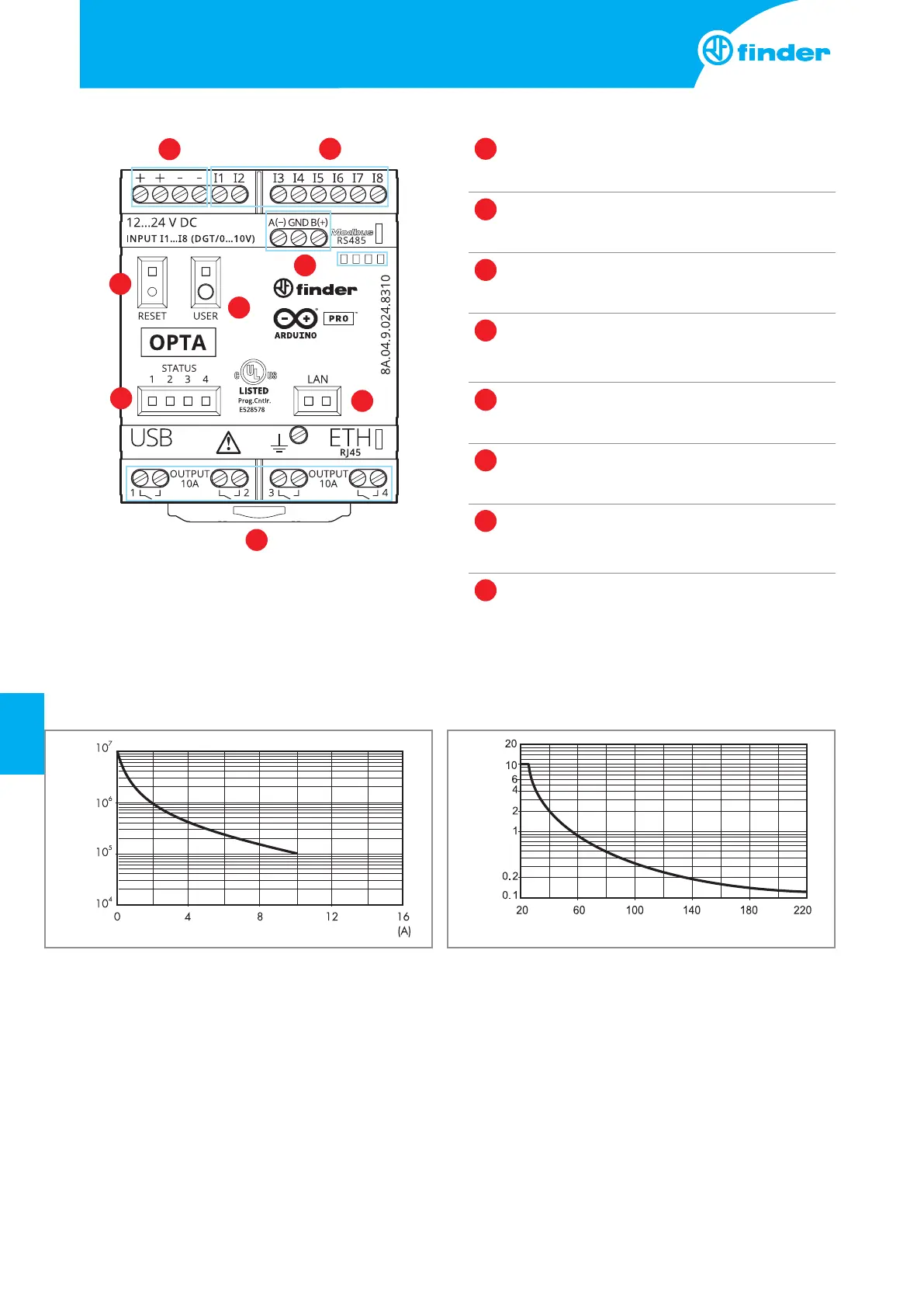
1
2
3
4
5
6
7
8
1
Supply terminals
12…24 V DC, Split terminals to facilitate wiring.
2
Input terminals
I1…I8 digital/analog (0…10 V) input configurable via IDE.
3
Output terminals
1…4 Output relay, 10 A 250 V AC, NO contact.
4
LED Status
1…4 LED Status configurable via IDE.
For exemple for 1…4 output relay LED ON = Contact CLOSE.
5
LED Ethernet port status
Status of ETH connection.
6
Modbus RS485 Port
Terminals for Modbus over RS485 protocol.
7
HARDWARE RESET
Button for hardware reset. BE CAREFUL. Press the 'RESET'
button with the tip of a small non-metallic insulated tool.
8
Programmable USER button
Button configurable via IDE by user, according to application
(ex. RUN/STOP, ON/OFF, BLE pair).
Contact specification
F 8A - Electrical life (AC) v contact current H 8A - Maximum DC1 breaking capacity
Cycles
DC breaking current (A)
DC voltage (V)
• When switching a resistive load (DC1) having voltage and current
values under the curve, an electrical life of ≥100·10
3
can be
expected.
• In the case of DC13 loads, the connection of a diode in parallel with
the load will permit a similar electrical life as for a DC1 load.
Note: the release time for the load will be increased.
6
I-2023, www.findernet.com
8A SERIES
Programmable Logic Relays
8A
SERIES