Patent Pending
Note: All power connections to be installed to local/national codes by a Certified Electrician. Finelite, Inc. • 30500 Whipple Road • Union City, CA 94587-1530 • (510) 441-1100 • Fax: (510) 441-1510 • www.finelite.com
9 of 13
© 2018 FINELITE, INC. ALL RIGHTS RESERVED. Form CE - 98532. 03/18
HP-2 / HP-4 / HP-6 Recessed or Regressed Spackle & Visible Flange Mitered Corner
Installation Instructions
This is a hypothetical build to show the capabilities of this luminaire family and mount type. Your build may vary.
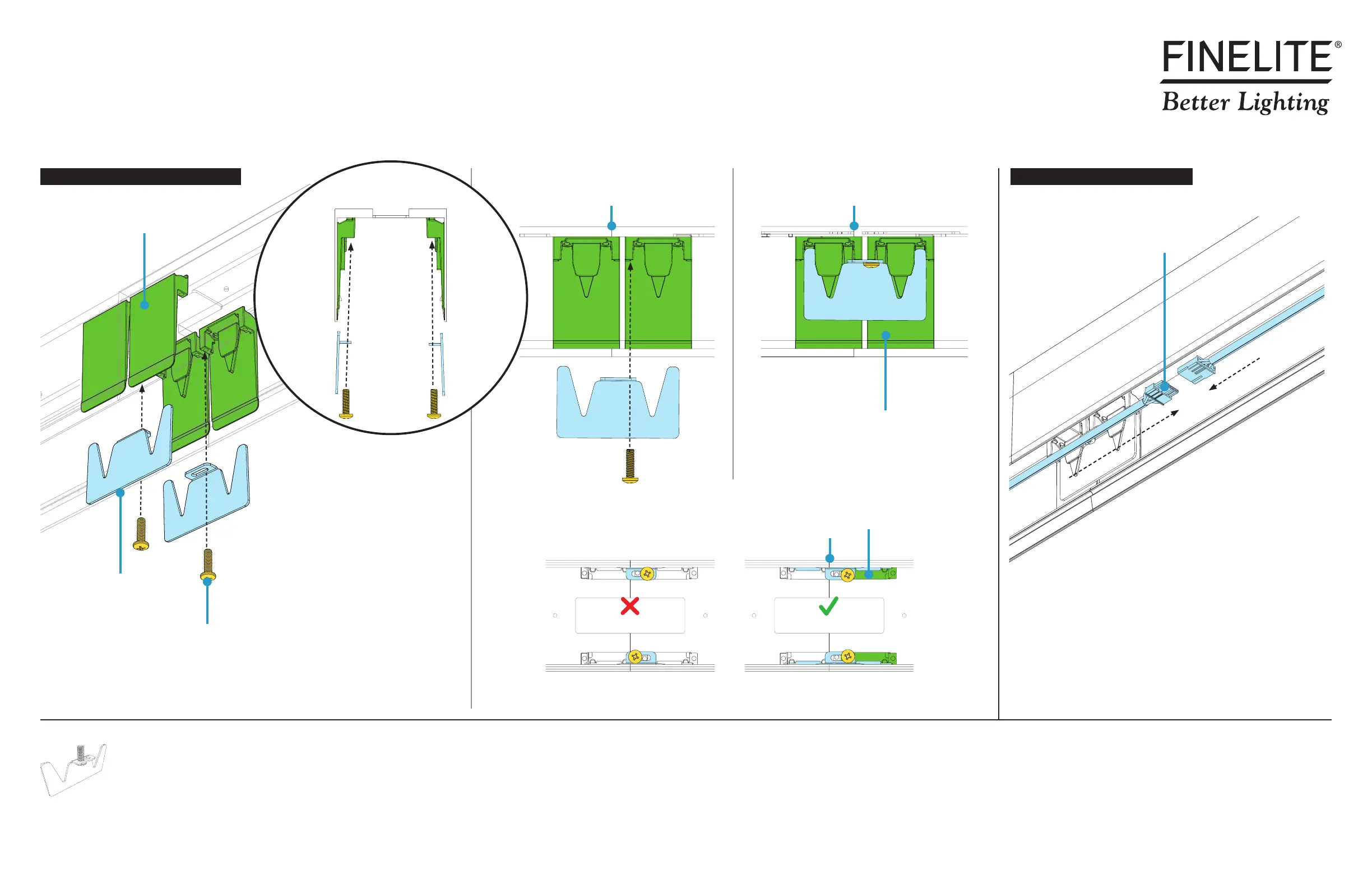
B. Make Electrical ConnectionsA. Secure Joint with Yoke Brackets
IN ALIGNMENT CORRECTLY INSTALLED
Joiner
Starter
Yoke Screws
(provided)
Aligner Sleeves
Yoke Brackets
(provided)
Step 6 - Securing Luminaire Joints
Yoke Bracket w/ Screw
#10-32 x 5/8" (provided)
• Connect plug-together wiring.
Luminaire Joint Luminaire Joint
YESNO
YOKE SCREW ALIGNMENT Bottom-Up View
Cross Section
View
Joiner
Starter
Plug-Together Wiring
Joiner
Aligner Sleeves
Joiner
Aligner Sleeves
Luminaire Joint
NOTE: Yoke screws should be installed directly across from each other, not diagonally, and in holes furthest from
the joint line. One yoke screw per one yoke bracket.
• Before installing yoke brackets, ensure the joining ends of luminaires meet flush and square.
• CRITICAL: Ensure yoke brackets properly engage with aligner sleeves.
• Secure joint by threading (but not yet tightening) yoke screws through yoke brackets and
into aligner sleeves.