EasyManua.ls Logo

FIP FLS F3.00 User Manual

FIP FLS F3.00
32 pages
To Next Page IconTo Next Page
Page #1 background imageLoading...
Page #1 background image
1
FLS F3.00
PADDLEWHEEL
FLOW SENSOR
SAFETY INSTRUCTIONS
General Statements
• Do not install and service the product without following the Instruction
Manual.
• This item is designed to be connected to other instruments which can be
hazardous if used improperly. Read and follow all associated instrument
manuals before using with it.
• Product installation and wiring connections should only be performed by
qualied sta󰀨.
• Do not modify product construction.
Installation and Commissioning Statements
• Remove power to the instrument before wiring input and output connections.
• Depressurize and vent the system before installing or removing the sensor.
• Check and conrm the chemical compatibility of the materials in contact
with the liquid.
• Do not exceed maximum specications using the instrument.
• To clean the unit, use only chemical compatible products.
Question and Answer IconNeed help?

Do you have a question about the FIP FLS F3.00 and is the answer not in the manual?

FIP FLS F3.00 Specifications

General IconGeneral
BrandFIP
ModelFLS F3.00
CategoryAccessories
LanguageEnglish

Summary

Safety Instructions

General Statements

Safety guidelines for general use, installation, and servicing of the product.

Installation and Commissioning Statements

Safety precautions to be followed during the installation and commissioning phases of the sensor.

Packing List

Description

Technical Data

General Technical Specifications

Covers general specifications like pipe size, flow rate, linearity, repeatability, enclosure, and wetted materials.

Specific Data for F3.00.H

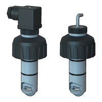
Details electrical supply, current, output signal type, and cable length for the F3.00.H model.

Specific Data for F3.00.C

Specific Data for F3.00.P

Standards and Approvals

Maximum Operating Pressure and Temperature

Pressure/Temperature Limits for F3.00.H or F3.00.P Sensor

Specifies the maximum operating pressure and temperature for F3.00.H and F3.00.P sensor variants across different body materials.

Pressure/Temperature Limits for F3.00.C Sensor

Specifies the maximum operating pressure and temperature for the F3.00.C sensor variant across different body materials.

Dimensions

Installation

Pipe Location Recommendations

Advises on selecting optimal placement within the pipeline for accurate flow measurement, showing common configurations.

Mounting Position Guidelines

Process Connection Procedure

Wiring

General Wiring Recommendations

Best practices for safe and effective electrical connections, emphasizing power supply conditions.

Wiring Diagrams Overview

Presents various wiring configurations for connecting the sensor to FLS instruments and PLCs.

Installation Fittings

K-Factor Tables

ISO Metric PVC Tee Fittings

K-factor data for ISO Metric PVC tee fittings for SDR 21 pipes.

ISO Metric Clamp Saddles for ISO SDR 21 pipes

K-factor data for ISO Metric clamp saddles for SDR 21 pipes.

BSP Female Threaded PVC Tee Fittings

K-factor data for BSP female threaded PVC tee fittings for BS PN12 pipes.

BS Solvent Welding PVC Tee Fittings

K-factor data for BS solvent welding PVC tee fittings for BS PN12 pipes.

NPT Female Threaded PVC Tee Fittings

ASTM SCH. 80 Clamp Saddles

K-Factor Tables: C-PVC Pipes

K-Factor Tables: PVDF Pipes

K-Factor Tables: PE Pipes

K-Factor Tables: Metal Pipes

K-Factor Correction Formula

Ordering Data

F3.00.H Series Ordering Information

Details part numbers, specifications, and weights for F3.00.H remote paddlewheel flow sensors.

F3.00.C Series Ordering Information

F3.00.P Series Ordering Information

F3.01 Series Ordering Information

Spare Parts