Do you have a question about the Fire-Lite Alarms MS-5024UD and is the answer not in the manual?
Lists the key features and capabilities of the MS-5024UD Fire Alarm Control Panel.
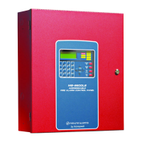
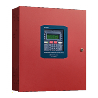
Details the front panel switches, displays, and LEDs for system interaction.
Explains the functions and connections of the integrated digital communicator.
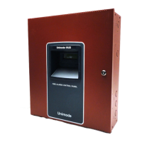
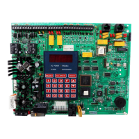
Describes the main circuit board and the system cabinet housing the components.
Details optional modules like RM-5F, CAC-5F, ADM-24, and RZA-5F.
Provides detailed technical specifications for AC power, battery, and initiating circuits.
Covers requirements for connecting the panel to the telephone network.
Details procedures for mounting the system cabinet to a wall.
Explains how to properly attach and secure the backbox to the mounting surface.
Explains primary AC power and secondary battery connections for system operation.
Describes the five zone input circuits and their configuration for devices.
Details DC power outputs, telephone connections, and notification appliance circuits.
Outlines essential rules for separating power-limited and nonpower-limited wiring.
Explains connections and wiring for the panel's digital communicator.
Introduces optional modules like ADM-24 and RZA-5F for enhanced functionality.
Covers the installation and configuration of the PRT-24 printer module.
Provides instructions on how to access the panel's programming mode using a code.
Details initial programming steps for central station numbers and communication formats.
Configures alarm verification and selects panel operation mode (Fire Panel/Communicator).
Configures zone functions, device types, and waterflow retard timer delays.
Configures NAC behavior, trouble reminders, and other system notification settings.
Explains how to reset all programmed entries back to factory default settings.
Describes the function of switches like RESET, SILENCE, and MODE in normal operation.
Explains panel displays, status messages, and key functions for operation.
Discusses system status monitoring, event priorities, and alarm response procedures.
Details alarm restoral actions and panel responses to supervisory conditions.
Explains how the panel indicates and reports system troubles and status changes.
Describes how to disable/enable zones and initiate a fire drill for evacuation.
Details the priority order for transmitting system events to a central station.
Details how to perform a one-man walktest of system zones and devices.
Explains how to access and view stored events from the History File.
Details how to use the internal voltmeter to check system voltages and diagnose issues.
Describes how to test system LEDs and print system data or status.
Explains the process of downloading program data to the panel from a service terminal.
Describes how to upload system data from the panel to a service terminal.
Discusses filtered power supply for the panel and external devices during standby.
Lists and describes the various operational modes of the control panel.
Lists and describes specific function modes like zone disable and fire drill.
| Type | Addressable Fire Alarm Control Panel |
|---|---|
| Number of Zones | 24 |
| Operating Voltage | 24 VDC |
| Operating Temperature | 32°F to 120°F (0°C to 49°C) |
| Zones | 24 |
| NAC Circuits | 4 |
| Maximum Signaling Line Circuits (SLCs) | 1 |
| Current Draw | 0.5 A |
| Battery Capacity | 18 AH |
| Maximum Number of Detectors per SLC | 198 |
| Relative Humidity | 10% to 93% (non-condensing) |