Do you have a question about the Fire-Lite Alarms MS-5UD Series and is the answer not in the manual?
Ensures proper system operation after programming or software changes.
Information regarding radio frequency energy emissions and compliance.
Compliance information for digital apparatus per Canadian regulations.
Recommendation to download the most current software version for products.
Instructions for providing comments and suggestions on documentation.
Lists NFPA standards this Fire Alarm Control Panel complies with.
List of Fire-Lite documents for compatibility and installation.
Lists the key features of the MS-5UD and MS-10UD panels.
Details AC power, battery, IDC, NAC, and relay specifications.
Describes the LCD display, key panel, and LED indicators.
Explains the functions and communication formats of the DACT.
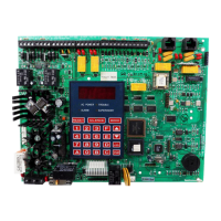
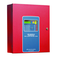
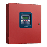
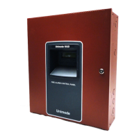
Lists the main components: Main Circuit Board, Power Supply, Cabinet, Batteries.
Details optional modules like CAC-5X, 4XTMF, and annunciators.
Covers telephone line requirements, RJ31X jacks, and FCC compliance.
Instructions for physically mounting the FACP backbox.
Details primary (AC) and secondary (battery) power connections.
Describes connection of initiating devices like smoke detectors and pull stations.
Details connection of notification appliances and relays.
Guidelines for separating power-limited and nonpower-limited wiring.
Explains DACT connection and wiring for telephone lines.
Procedures for installing optional modules.
Installs CAC-5X to convert Class B to Class A wiring.
Installs the 4XTMF module for reverse polarity/municipal box.
Details connecting ANN-BUS peripherals.
Information on calculating wire distance for ANN-BUS modules.
Setting unique addresses for ANN-BUS devices.
Installation and operation of the ANN-80 annunciator.
Technical specifications for the ANN-80.
Steps for mounting and wiring the ANN-80.
How to mount the ANN-80 annunciator.
Procedure to open and close the ANN-80 cover.
Connecting the ANN-80 to the FACP.
Connecting a printer to the FACP for event logging.
Technical specs for the ANN-S/PG module.
Details on connecting and setting up the PRN-6F printer.
How to connect the PRN-6F printer.
Configuring printer settings like font and baud rate.
Connecting LEDs for custom annunciators.
Diagram of the ANN-I/O board.
Technical specs for the ANN-I/O module.
How to connect the ANN-I/O to the FACP.
Detailed wiring for ANN-I/O module LEDs.
Provides LED indication for system faults and zones.
Diagram of the ANN-LED board.
Technical specs for the ANN-LED module.
Instructions for installing the ANN-LED module.
Connecting the ANN-LED to the FACP.
Provides 10 programmable Form-C relays.
Diagram of the ANN-RLY board.
Technical specs for the ANN-RLY module.
Instructions for installing the ANN-RLY module.
Connecting the ANN-RLY to the FACP.
Connects an audio panel to the FACP via ANN-BUS.
Overview of field programmable options via keypad or computer.
Procedures for initial system programming and setup.
Explanation of navigating programming menus and screens.
Details on accessing programming levels via passwords.
Covers advanced programming options for system setup.
Programming for individual input zones (devices).
Configuration options for notification appliance circuits.
Programming the function of the panel's Form-C relays.
Configuration of system-wide settings like timers and banners.
Setting delays for PAS, Pre-Signal, and Waterflow.
Customizing the display banner text.
Setting the system clock and date.
Enabling audible reminders for troubles.
Configuring the panel for Canadian specifications.
Option to disable the onboard battery charger.
Configuration for installed option modules.
Enabling and configuring ANN-BUS modules.
Enabling the ANN-BUS communication circuit.
Addressing and identifying ANN-BUS modules.
Automated process for setting up ANN-BUS modules.
Configuring printer interface options.
Mapping LEDs for custom annunciators.
Configuring ANN-80 annunciator functions.
Configuring ANN-RLY relay module functions.
Configuring ANN-AUDIO panel settings.
Configuring the onboard digital alarm communicator.
Setting up the primary phone line for DACT.
Setting up the secondary phone line for DACT.
Configuring reporting to the central station.
Entering central station phone numbers.
Limits DACT trouble calls to the central station.
Setting up remote access parameters.
Setting the number of rings before answering a call.
Enabling or disabling phone line supervision.
Viewing and erasing system event history.
Accessing the event history log.
Clearing the system event history.
Performing system tests.
Resetting the panel's program to defaults.
Changing access passwords for programming levels.
Accessing maintenance-specific programming options.
Enabling or disabling specific input zones.
Viewing and erasing maintenance history.
Performing walktests in maintenance mode.
Setting system time and date in maintenance mode.
Describes the function of each button on the FACP keypad.
Silences piezo, changes LEDs, and steps through events.
Silences NACs and indicates alarm silence.
Activates NACs for drill purposes.
Resets system, performs lamp test, and clears alarms.
Explains the meaning of each LED on the FACP.
Describes the system status and functions during normal operation.
Details how the system behaves and displays trouble conditions.
Describes system behavior and display during alarm conditions.
Describes system behavior and display during supervisory conditions.
Describes system behavior for process monitor events.
Describes system behavior for hazard/tornado events.
Describes system behavior for medical alert events.
How to disable or enable input zones and NACs.
Behavior of waterflow circuits.
Describes detector behavior like maintenance alerts.
Details the FACP's real-time clock functionality.
Programming NACs for different coded outputs.
Feature to delay NAC activation for visual verification.
Feature to delay panel activation for smoke detectors.
Configuration of special system timers.
Timer to prevent silencing after an alarm.
Timer to automatically silence notification appliances.
Provides audible reminders for troubles.
Timer to delay waterflow alarm activation.
Feature to reduce false alarms for smoke detectors.
Procedure for testing the fire alarm system.
Viewing the system's current status and programmed features.
Viewing status and programming of input zones.
Viewing status and programming of NAC circuits.
Viewing programmed options for each relay.
Viewing system-wide configuration settings.
Viewing the configured timer settings.
Viewing daylight savings time settings.
Viewing the system's event history.
Printing system data and status.
Viewing ANN-BUS system status and configuration.
Viewing central station reporting status.
Viewing phone line configuration status.
Viewing service terminal status.
Lists the priority order for transmitting events to central stations.
Enabling and configuring remote download capabilities.
Procedures for uploading and downloading panel programs.
Details security measures for data transfer.
Introduction to calculating power supply currents and battery size.
Determining AC branch circuit current requirements.
Calculating the total current draw for system components.
Determining the required battery size for backup power.
NFPA 72 requirements for standby power.
Guidance on choosing and placing batteries.
Explains the structure of Ademco Contact ID transmission strings.
Example of a central station receiver printout.
Lists NFPA 72 standards applicable to this system.
Requirements for central station communication.
Requirements for auxiliary fire alarm systems.
Requirements for proprietary fire alarm systems.
Chart detailing FACP circuit wire types, limitations, and gauges.
Wiring table for FLPS-3 power supply models.
Wiring table for FLPS-7 power supply models.
| Number of Zones | 5 |
|---|---|
| NACs | 2 |
| Operating Temperature | 32°F to 120°F (0°C to 49°C) |
| Type | Fire Alarm Control Panel |
| Operating Voltage | 120 VAC, 50/60 Hz |
| Maximum Signaling Current (NAC) | 2.5 A |
| Total System Current | 6 A |
| Battery Capacity | 18 Ah |
| Battery Charging Current | 1 A |
| Auxiliary Power Output | 24 VDC, 500 mA |
| NAC Outputs | 24 VDC, 2.5 A |
| Relay Contacts | 2 Form-C |
| Dimensions | 14.5" x 3.5" |