Do you have a question about the FireAngel CO-9X-10 and is the answer not in the manual?
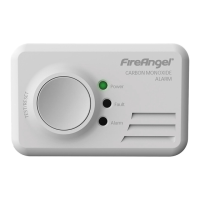
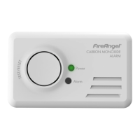
Detects CO levels and provides early warning of toxic CO.
Monitors carbon monoxide levels constantly.
Minimizes false alarms from household contaminants.
Emits an 85dB alarm at 1m for emergency alerts.
Button for testing and resetting the detector functions.
Automatic self-checks ensure correct operation.
Simple installation and portability, ideal for travel.
Certified to EN 50291-1 and EN 50291-2 standards.
The product comes with a 10-year warranty.
Details symptoms of mild, medium, and extreme CO poisoning.
Max allowable CO concentration for 8-hour exposure for adults.
CO level causing mild symptoms after 2-3 hours.
CO level causing headaches in 1-2 hours, life-threatening after 3 hours.
CO level causing severe symptoms within minutes, death within hours.
Lists common sources of carbon monoxide emissions.
Lists actions to avoid to prevent CO exposure and ensure safety.
Lists recommended practices for safe appliance use and detector installation.
Guidance on selecting the optimal room for CO detector placement.
Recommends placement in rooms where occupants spend time and might miss alarms.
Advises installing a detector in every bedroom for safety.
Prioritize placement near flueless or open-flued appliances.
Suggests placing the detector in frequently used rooms.
Specific advice for bedsits, placing detector away from cooking appliances.
Placement advice for detectors near infrequently used appliances like boiler rooms.
Details on precise placement within a room relative to sources.
Specifies optimal horizontal distance from potential CO sources.
Placement advice for rooms with partitions, keeping detector on the same side as the source.
Guidance for sloped ceilings, placing detector at the highest point.
Specific wall mounting instructions for the detector.
Recommends mounting the detector near the ceiling on a wall.
Specifies height relative to doors and windows for wall mounting.
Minimum distance requirement from the ceiling for wall mounting.
Specific ceiling mounting instructions for the detector.
Minimum distance from walls and obstructions for ceiling mounting.
Placement for sleeping rooms or rooms distant from appliance.
Advises placing detectors near occupant's breathing zone in bedrooms/remote rooms.
Lists locations where the detector should not be installed.
Avoid installing in enclosed spaces like cupboards or behind curtains.
Do not place where furniture or other items can obstruct it.
Avoid installing directly above a sink due to potential moisture.
Avoid placement next to doors or windows.
Do not install next to extractor fans.
Avoid placement near air vents or ventilation openings.
Do not install in extreme temperature ranges (-10°C to 40°C).
Avoid dusty areas that could block the sensor.
Do not install in damp or humid locations like bathrooms.
Avoid placement very close to cooking appliances.
Keep detector at least 1m away from mobile phones.
Specific installation advice for caravans.
Install in caravans near combustion appliances, following general rules.
In single-space caravans, one alarm is adequate if it includes sleeping area.
Separate sleeping areas in caravans need their own alarms.
Avoid mounting directly above heat or steam sources.
Mount detector 1-3m from the nearest edge of the CO source.
Step-by-step instructions for installing the CO detector.
Emphasizes professional installation by a competent individual.
Recommends recording the installation date on the detector.
Instructions for mounting the detector on a wall or ceiling.
Use the supplied screws and follow template for drilling and mounting.
Instructions for placing the detector on a shelf.
The detector base is designed for stable shelf placement.
Shelf placement must follow the same location guidelines as wall/ceiling mounting.
Specifies the required spacing for drill holes for mounting.
The detector has an integrated power pack for its entire life.
Activate by pulling the disabling tab to remove the disabling clip.
Activated detector shows a green flashing LED every minute.
Test functionality by pressing the Test/Reset button weekly.
Warning about potential hearing damage from prolonged close exposure to the sounder.
The power pack is designed to last for the product's 10-year lifespan.
Detector is inactive if power pack drains, offering no protection.
Extreme temperatures can shorten the power pack's lifespan.
Instructions for deactivating the power pack for travel or storage.
Detector is portable and can be deactivated for travel or storage.
Deactivate by inserting the metal clip into the disabling socket.
Confirm deactivation by checking for no sound when pressing the test button.
A paperclip can substitute the disabling tab if lost.
Details the functions of the Test/Reset button.
Allows testing of sounder, power pack, and internal circuitry.
Enables sensor testing by introducing a CO source.
Silences alarms for low CO levels (<50ppm) temporarily.
Describes the weekly test procedure for sounder, power pack, and circuitry.
Instructions for testing the carbon monoxide sensor.
Suggests using incense sticks or cigarettes for sensor testing.
Smoke from candles/matches is insufficient for sensor testing.
Clarifies that the detector is for CO, not smoke detection.
Sensor testing must be conducted by a responsible adult.
Sensor test is annual; frequent testing reduces power pack life.
Suggests incense sticks for CO testing as an alternative to cigarettes.
Advises reading all steps before starting the sensor test.
First step for testing: unhooking wall/ceiling mounted detectors.
Second step: cover vents, press button, observe LED/sounder for test readiness.
Third step: light and prepare the CO source (incense/cigarette), then extinguish lighter/match safely.
Fourth step: position detector, hold CO source below it, observe indicator response.
Fifth step: detector returns to normal mode after test; move CO source away.
Safely extinguish and dispose of the CO source after the test.
Sensor test auto-stops if 50ppm is not reached within 3 minutes.
Details the time it takes for the alarm to sound at different CO concentrations.
Alarm sounds between 60-90 mins at 50ppm CO exposure.
Alarm sounds between 10-40 mins at 100ppm CO exposure.
Alarm sounds within 3 mins at 300ppm or higher CO exposure.
Explains the fault or low power pack indicator signal.
Fault/low power signal is a chirp and flashing yellow LED, indicating issues or low battery.
End-of-life signal indicates unit needs replacement after 10 years of activation.
The end-of-life signal is not related to CO detection.
Advice on action for out-of-warranty or in-warranty end-of-life units.
Detector should be replaced after 10 years due to sensor/power pack lifespan.
General maintenance recommendations for the detector.
Perform weekly tests of sounder, power pack, and circuitry.
Conduct the sensor test once per year.
Keep the detector clean by vacuuming with a soft brush.
Precautions to prevent sensor contamination.
Clean only with a slightly damp cloth, no cleaning solutions.
Avoid painting the detector as it can affect performance.
Do not spray aerosols near the detector due to potential damage.
Keep solvent-based products away from the detector.
Avoid certain substances in caravans that can affect detector reliability.
Protect detector from fumes during redecoration by storing it safely.
Report any failed tests to the Technical Support Team.
Do not attempt to repair or open the detector; this voids the warranty.
A loud alarm indicates dangerous CO levels; take immediate action and never ignore it.
Advise users to review manual for alarm response procedures.
Steps to take immediately when the alarm sounds.
Maintain calm and ventilate the property by opening doors/windows.
Stop and turn off all fuel-burning appliances.
Evacuate the property, leaving doors and windows open for ventilation.
Contact fuel supplier's emergency number; keep it visible.
Space to write down fuel supplier emergency contact details.
Do not re-enter until the alarm ceases, allowing sensor to clear.
Seek immediate medical attention for CO poisoning symptoms.
Do not use appliances until inspected by a qualified, Gas Safe registered engineer.
Emergency contact number for National Gas Service.
Contact information for the Gas Safe register.
Advisory service contact for domestic and solid fuel appliances.
Trade association contact for solid fuel engineers.
Trade association contact for Oil Fired Appliance engineers.
Contact for the National Association of Chimney Sweeps.
Contact for the Institute of Plumbing and Heating Engineers.
Details specifications, standards, and operational parameters of the detector.
Lists the technical specifications of the CO detector.
Identifies the specific model of the CO detector.
Specifies the sensor technology used in the detector.
Indicates the expected lifespan of the detector's sensor.
States the loudness of the alarm at a specific distance.
Defines the operational temperature range for the detector.
Specifies the acceptable operating humidity range.
Lists the certification standards the detector meets.
Detector is designed for continuous CO monitoring, meeting European standards.
Details the time it takes for the alarm to sound at different CO concentrations.
Apparatus may not protect those at special risk; consult doctor if unsure.
CO detectors are not substitutes for smoke or gas detectors.
The detector unit must be replaced after 10 years of operation.
Proper disposal of waste electrical products, advising recycling and local checks.
Deactivate power pack before disposal using the disabling tab or a paperclip.
Do not attempt to open or burn the detector unit.
Details the terms and conditions of the 10-year product warranty.
Details the warranty coverage provided for the detector.
Warranty covers defects in materials/workmanship for 10 years from purchase date.
Replacement is free within 10 years if returned with proof of purchase.
Warranty on replacement units covers the remainder of the original warranty period.
Company may offer alternative products if the original is unavailable.
Warranty is for the original retail purchaser and is non-transferable.
Proof of purchase is necessary to claim the warranty.
Lists exclusions and limitations of the product warranty.
Excludes damage from misuse, accident, or improper application.
Excludes damage from events beyond company control like Acts of God.
Warranty does not extend to retailers, service centres, or distributors.
Third-party modifications to warranty are not recognized.
Company not liable for incidental or consequential damages from warranty breach.
Implied warranties are limited to 10 years, as permitted by law.
Warranty does not affect statutory rights; liability limited for damages.
Steps for returning the product for testing or warranty claims.
Contact technical support first for troubleshooting before returning the product.
Support team provides a returns authority number if fault cannot be resolved remotely.
Return instructions for warranty claims, including deactivation, packing, and proof of purchase.
Overview of Sprue Safety Products' range of home safety devices, directing to their website.
Instruction to tape the disabling tab in this location for future use.
| Type | Carbon Monoxide Alarm |
|---|---|
| Sensor Technology | Electrochemical |
| Battery Life | Up to 10 years |
| Alarm Volume | 85 dB |
| Test Button | Yes |
| LED Indicator | Yes |
| Operating Humidity | 30% to 90% RH |
| Weight | 150 g |
| Power Supply | Battery |
| Operating Temperature | 0°C to 40°C |
| Product Dimensions | 120mm x 75mm x 40mm |
| Standards Compliance | EN 50291 |