TECHNICAL SPECIFICATION
Type Iden ti fi ca tion Value: 161
Sys tem Com pat i bil ity: Use only with FC Fire Alarm Con trol lers
En vi ron ment: In door Ap pli ca tion only
Op er at ing Tem per a ture: -25 to +70
o
C
Stor age Tem per a ture: -40 to +80
o
C
Op er at ing Hu mid ity: Up to 95% non-con dens ing
Di men sions (HxWxD): 87 x 148 x 14 mm
Mount ing Re quire ments: One FC backbox sur face mount
Bat tery Re quire ments:
Standby Cur rent: 0.46mA max
Alarm Cur rent: 4.5mA max
Ad dress able De vice Con di -
tions: – Nor mal
– Ac tive
– Out put Stuck
– De vice Type In valid
– De vice No Re sponse
Re lay Con tact Rat ing: DC – 2A @ 24V dc
+ Note: The mod ule must not be used to switch mains volt ages
Rec om mended Wire Size: Min. 1.5 mm
2
Max. 2.5 mm
2
Electromagnetic Compatibility
The FC410RIM com plies with the fol low ing:
Ø prod uct fam ily stan dard EN50130-4 in re spect of Con ducted Dis tur -
bances, Ra di ated Im mu nity, Elec tro static Dis charge, Fast Tran sients
and Slow High En ergy;
Ø EN50081-1 for emis sions.
INTRODUCTION
The FC410RIM Re lay In ter face Mod ule pro vides one volt-free re lay change -
over con tact on a latch ing re lay. The re lay is con trolled by a com mand sent
from the FC fire con trol ler via the ad dress able loop. The re lay state (ac ti -
vated, de ac ti vated or stuck) is re turned to the con trol ler.
FEATURES
FC410RIM fe a tu res in clu de the fol lo wing:
Ø Addres sa ble fun ctio na lity.
The con trol pa nel sends a com mand to ope ra te the re lay, then re ports an
ac ti va ted or de ac ti vated state back to the pa nel thro ugh the use of a set of
con tacts de di ca ted to mo ni tor the sta te of the re lay.
Ø One volt-free dry con tact re lay out put.
Ø Out put to dri ve a high vol ta ge re lay HVR800.
Ø LED sta tus in di ca tor which is nor mally off. When the FC410RIM re ce i ves
a com mand to ac ti va te, the LED lights.
WIRING & INSTALLATION NOTES
! CAUTION:THE O+ AND O- TERMINALS MUST NOT BE USED.FOR
CONNECTING THE FC410RIM TO AN HVR800, SEE PUBLICATION
17A-03-HVR OR 120-415-528.
The fol low ing notes ap ply:
1) There are no user-re quired set tings (switches, head ers) on the
FC410RIM. All wir ing must be free of earths.
2) All wir ing must con form to the ap pli ca ble stan dards.
3) See Fig ure 4 for FC410RIM Sim pli fied Wir ing Di a gram.
4) For 24V dc pow ered ap pli ca tions, only use a reg u lated sup ply suit able
for fire pro tec tive sig nal ling ser vice.
5) For pow ered cir cuit op er a tion, route the pos i tive con duc tor through the
FC410RIM to the ex ter nal de vice, while con nect ing the com mon (neu -
tral) con duc tor to the ex ter nal cir cuit.
6) For dry con tact switch ing, con nect the ex ter nal cir cuit to the COM and N/O
or N/C ter mi nals for nor mally open or nor mally closed op er a tion as re quired.
7) Ver ify that re lay wir ing is cor rect for the FC410RIM be fore con nect ing to
the ad dress able loop cir cuit.
8) For con nec tion to an HVR800 High Volt age Re lay Mod ule, re fer to In -
stal la tion Sheet 17A-03-HVR or 120-415-528.
INSTALLATION TO FC470CV DOUBLE GANG COVER
1) As sem ble the FC410RIM to FC470CV Dou ble Gang cover, us ing the
four screws and wash ers pro vided.
2) Snap on the an cil lary hous ing PCB cover.
3) Fit cover onto FC backbox.
ADDRESS SETTINGS
The FC410RIM has a de fault fac tory set ad dress of 255, this must be set to
the loop ad dress of the de vice us ing the FC490ST Loop Ser vice Tool. The
FC410RIM may be pro grammed with the ad dress prior to be ing in stalled by
us ing the in ter nal pro gram ming port (see Fig.2) or af ter be ing in stalled by
us ing the pro gram ming port on the front cover (see Fig.3).
+ Note: once the ad dress has been pro grammed, take note of the de vice
lo ca tion and ad dress num ber, to in clude on site draw ings.
CABLING
The max i mum sec tion of the ca ble that can be con nected at any one ter mi -
nal is 2.5mm
2
. The sec tion is cal cu lated based on the char ac ter is tics of the
ca ble and the load.
ORDERING INFORMATION
FC410RIM: Re lay In put Mod ule:
FC470CV: Dou ble-Gang cover
RECYCLING INFORMATION
Cus tom ers are rec om mended to dis pose of their used equipments (pan els,
de tec tors, si rens, and other de vices) in an en vi ron men tally sound man ner.
Po ten tial meth ods in clude re use of parts or whole prod ucts and re cy cling of
prod ucts, com po nents, and/or ma te ri als.
WASTE ELECTRICAL AND ELECTRONIC EQUIPMENT (WEEE)
DIRECTIVE
In the Eu ro pean Un ion, this la bel in di cates that this prod uct
should NOT be dis posed of with house hold waste. It should be
de pos ited at an ap pro pri ate fa cil ity to en able re cov ery and re -
cy cling.
The ma nu fac tu rer re ser ves the right to chan ge the tec hni cal spe ci fi ca tions
of this pro duct wit ho ut prior no ti ce.
ENGLISH
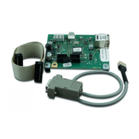
FIG. 1 FC410RIM Re lay In ter face Mod ule
 Loading...