FireClass FC410RIM
Fixing Instructions Doc. version 4.0 3/12
ENGLISH
Technical specification
Battery Requirements
Addressable Device Conditions
– Normal
– Active
– Output Stuck
– Device Type Invalid
– Device No Response
Relay Contact Rating
DC – 2A @ 24V dc
Note: The module must not be used to switch
mains voltages.
Recommended Wire Size:
Min. 1.5 mm
2
Max. 2.5 mm
2
Electromagnetic compatibility
The FC410RIM complies with the following:
product family standard EN50130-4 in respect
of Conducted Disturbances, Radiated Immu-
nity, Electrostatic Discharge, Fast Transients
and Slow High Energy;
EN50081-1 for emissions.
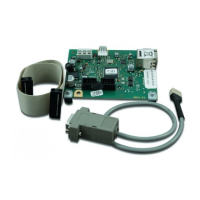
Introduction
The FC410RIM Relay Interface Module provides
one volt-free relay changeover contact on a lat-
ching relay. The relay is controlled by a command
sent from the FC fire controller via the addressa-
ble loop. The relay state (activated, deactivated
or stuck) is returned to the controller.
Features
FC410RIM features include the following:
Addressable functionality. The control panel
sends a command to operate the relay, then
reports an activated or deactivated state back
to the panel through the use of a set of con-
tacts dedicated to monitor the state of the
relay.
One volt-free dry contact relay output.
Output to drive a high voltage relay HVR800.
LED status indicator which is normally off.
When the FC410RIM receives a command to
activate, the LED lights.
Wiring & installation notes
The following notes apply:
1 There are no user-required settings (swit-
ches, headers) on the FC410RIM. All wiring
must be free of earths.
2 All wiring must conform to the applicable
standards.
Type Identification
Value
161
System
Compatibility
Use only with FC Fire
Alarm Controllers
Environment Indoor Application
only
Operating
Temperature
-25 to +70
o
C
Storage
Temperature
-40 to +80
o
C
Operating Humidity Up to 95% non-
condensing
Dimensions
(H x W x D)
87 x 148 x 14 mm
Mounting
Requirements
One FC backbox
surface mount
Standby Current 0.46 mA max
Alarm Current 4.5 mA max
PRECAUCIÓN
The O+ and O- terminals can only be
used for connecting an FC410RIM to an
HVR800. See document
120.415.528_17A-03-HVR for more
information.
CAUTION