FIRECLASS Fire detection system Panel Accessories
Fixing instructions Doc. version 1.0 3/12
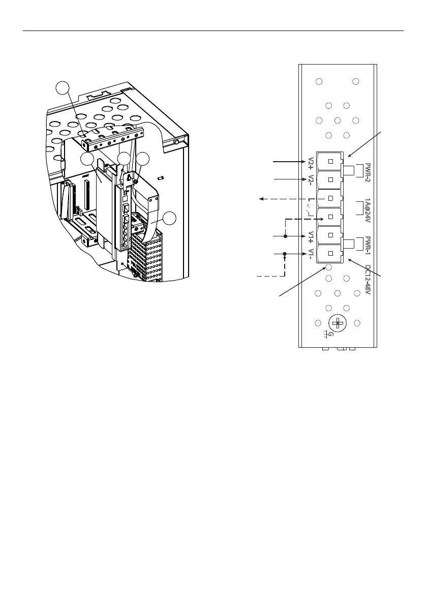
Fig. 2: Mounting the Ethernet switch and slot cage
holder into the slot cage.
1 – Ethernet switch
2 – Slot cage holder
3 – Screws
4 – Slot cage holes
5 – Fibre-optic holder
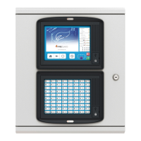
+24V
(&Ͳ&/-XT7)
-
-
ISOL IN +
ISOL IN -
+24V
(&Ͳ&/-XT6)
Pin 1
Pin 6
Reset
buƩon
[1]
Fig. 3: POS800 connectors overview
The dashed line indicates optional switch fault
monitoring.
[1] Press the reset button for 10 seconds to restore the
switch to the factory default configuration.