NOTE: DIAGRAMS & ILLUSTRATIONS NOT TO SCALE.
2
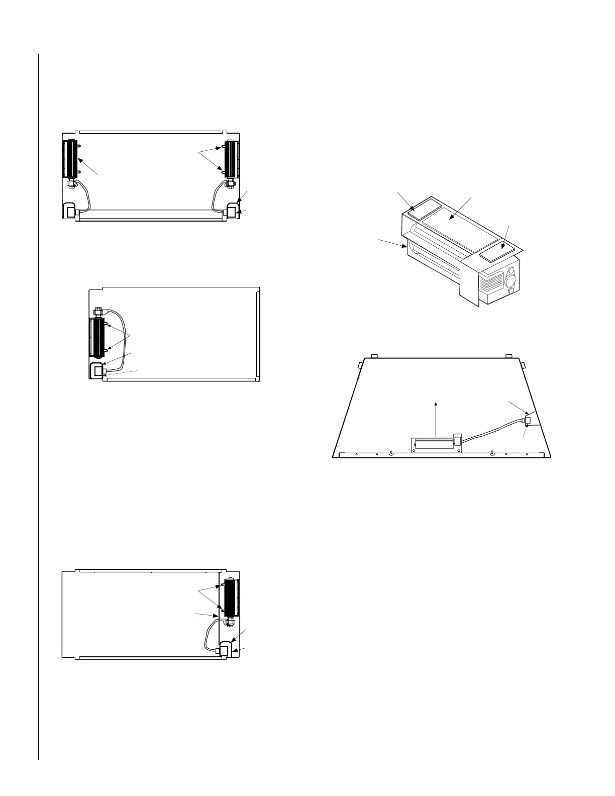
Step 6. D - Wood-burning fireplaces (other than vent-free) -
Place the two mating halves of each of the two Velcro sections together.
Peel the backing from one side of both of the mating pairs and stick the
pairs to the back of the blower housing as shown in
Figure 5
.
Wipe the inside surface of the bottom of the unit of any excess oil or debris.
Peel the backing from the other side of the two mated Velcro strips.
Slide the blower assembly through the front opening of the unit (avoiding
any contact between the sticky blower bottom and the cabinet). Position
the blower assembly as shown in
Figure 6
, pressing firmly down on the
blower in order to provide a positive blower to base attachment.
Step 6. C - Gas Fireplaces - Multi-open vent-free units -
Open all remaining bottom hinged-panels. Remove the blower shield
located across the inside right section of the unit.
See Figure 4
. Also
refer to the installation instructions packaged with the fireplace for ad-
ditional information on shield removal. Slide the blower assembly
through the closest opening to the flue side of the cabinet base. Posi-
tion the blower assembly so that the tabs (located on the cabinet base)
are seated in the notches of the blower bracket. Bend the tabs over to
secure the blower assembly. Reinstall the blower shield with the blower
cord routed to the electrical outlet.
Figure 4
Figure 5
Figure 6
BLOWER MOUNTING TABS
BLOWER
JUNCTION
BOX
ELECTRICAL
OUTLET
BLOWER INSTALLATION
MULTI-OPEN CATALYST AND VENT-FREE GAS FIREPLACE
(See-through, Peninsula)
BLOWER SHIELD
BLOWER
BLOWER SECURED
TO BASE WITH
VELCRO STRIPS
JUNCTION BOX
ELECTRICAL OUTLET
AIR FLOW
DIRECTION
BLOWER CENTERED SIDE TO SIDE AT THE FRONT OF THE UNIT
BLOWER INSTALLATION WOOD-BURNING FIREPLACES
(OTHER THAN VENT-FREE)
INSTALLING VELCRO STRIPS TO BLOWER BASE
MATING PAIR OF VELCRO STRIPS
BLOWER
GASKET
MATING PAIR
OF VELCRO
STRIPS
Figure 3
BLOWER
JUNCTION BOX
ELECTRICAL OUTLET
BLOWER INSTALLATION
MULTI-OPEN DIRECT VENT GAS FIREPLACE
(Corner Right)
BLOWER MOUNTING TABS
Step 6. B - Gas Fireplaces - Multi-open direct vent units -
Open all remaining bottom hinged-panels. Slide the blower assembly
through the closest opening to the flue side of the cabinet base. Position
the blower assembly so that the tabs (located on the cabinet base) are
seated in the notches of the blower bracket. Bend the tabs over to secure
the blower assembly.
See Figure 2 or 3
.
Figure 2
BLOWER
MOUNTING
TABS
BLOWER
JUNCTION
BOX
ELECTRICAL
OUTLET
BLOWER INSTALLATION
MULTI-OPEN DIRECT VENT GAS FIREPLACE
(See-through, Peninsula, Corner Left)
BLOWER MOUNTED
HERE ON MPD35ST
MODEL
Step 7. Install the field-provided ON/OFF switch (FBK-100 Kits) or
the kit-provided variable speed control (FBK-200 Kits) in a convenient
location on a wall, near the fireplace.
Step 8. Route a 3-wire, 120Vac power line to the ON/OFF switch (FBK-
100 kits) or variable speed control (FBK-200 kits) as shown in
Figure 7.
Then route the wires to the unit’s junction box. Remove the receptacle by
removing the two securing screws. Connect the supply wires to the
receptacle as shown in
Figure 7,
ensuring that the polarity (as determined
by the colors of the wires) is exactly as shown. Reinstall the receptacle.
 Loading...