NOTE: DIAGRAMS & ILLUSTRATIONS NOT TO SCALE.
4
Printed in U.S.A. © 2001 by Lennox Hearth Products
P/N 750,028M REV. E 03/2006
The manufacturer reserves the right to make changes at any time, without notice, in design,
materials, specifications, prices and also to discontinue colors, styles and products.
Consult your local distributor for fireplace code information.
1110 West Taft Avenue - Orange, CA 92865
Models UVFRC-4228, UVFRC-4228-H
UVFRC-3628 and UVFRC-3628-H :
Reinstall the bottom refractory panel that was
removed on
Step 1
(see
Figure 9 )
.
Models UVF-36:
Reinstall the blower access panel that was
removed on
Step 1
(see
Figure 10 )
.
Universal Vent Free Fireboxes
Installation Instructions -
FBK-100 or FBK 200 Blower Kits
JBK Junction Box Kit
Step 1. Follow the instructions below for the
model you are installing:
Models UVFRC-4228, UVFRC-4228-H,
UVFRC-3628 and UVFRC-3628-H:
Lift out the bottom refractory panel
(see
Figure 9 )
.
Models UVF-36 - Using a screwdriver remove
the screw from the blower access panel as
shown in
Figure 10.
Slide the panel to the
right until the flange clears the opening. Re-
move the panel and set aside.
Step 2. Remove the rectangular knock-out
(for J-Box) on the right side of the unit.
Install the junction box and electrical outlet
below the firebox floor into the rectangular
opening on the right side cabinet panel
where you removed the knock-out (
see
Figures 11 & 12
). The junction box/
electrical kit is sold separately.
Note:
Pass the wires through the hole, then
squeeze the J-Box flanges together to fit into
opening.
Step 3. Loosely tie a knot in the power cord
to take up slack (see
Figure 13 )
.
Step 4. Locate the tabs shown in
Figure 14.
Position the blower assembly so that the
tabs (located on the cabinet base) are seated
in the notches of the blower bracket. Bend
the tabs over to secure the blower assembly
(see
Figure 15 )
.
Step 5. Plug blower power cord into the
J-Box electrical outlet.
Step 6. Connect electrical outlet and switch
wires to the power supply; 3-wire, 120 VAC,
60 Hz, 1 ph power supply (see
Figure 8 )
.
FBK-100 Kits - Install a field-provided (or P/N
85L87) ON/OFF wall switch in a convenient
location on a wall, near the fireplace.
FBK-200 Kits - Install the kit-provided vari-
able speed control (rheostat) in a convenient
location on a wall, near the fireplace.
Step 7. Follow the instructions that follow
for the model you are installing:
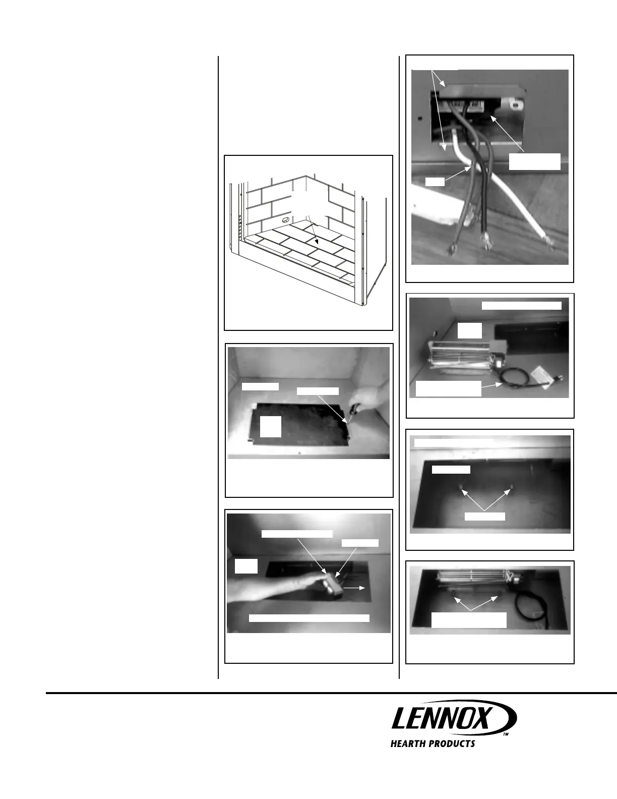
Lift Out Bottom Refractory Panel
Models
UVFRC-4228, UVFRC-4228-H,
UVFRC-3628 and UVFRC-3628-H
Bottom
Refractory
Panel
Figure 9
Figure 10
Remove Screw, Then Lift Out Blower Access Panel
(Model UVF-36)
Firebox Floor
Remove Screw
Blower
Access
Panel
Figure 11
(Model UVFRC-4228 Shown)
Firebox
Floor
J-Box Flange
Install Into Side Wall Rectangular Opening
J-Box & Electrical Outlet
J-Box And
Electrical Outlet
J-Box Flanges
Wires
Right Outside Cabinet Panel
Figure 12
Figure 13
Figure 14
Figure 15
NOTE: DIAGRAMS & ILLUSTRATIONS NOT TO SCALE.
Loose Knot In Power
Cord To Take Up Slack
Firebox
Floor
Model UVFRC-4228 Shown
Locating Tabs
Cabinet Base
Model UVFRC-4228 Shown
Bend Locating Tabs Over
(Into Notches)
Model UVFRC-4228 Shown
 Loading...