Page 2 of 8
TOTALPAC
2
® Integrated Fire Protection System
Air Supply
FM-072G-0-06 G
(when supplied). Observe all applicable codes for wiring of
the unit.
Connect non-energized AC power to the air compressor.
Refer to figure below and FIELD WIRING DIAGRAM.
.1 Connect the wire providing in-coming voltage to the
terminal TBB #6.
.2 Connect the neutral wire to the terminal marked TBB #5.
.3 Connect the ground wire to the terminal marked TBB #4.
Note: TBB #1, 2 & 3 when system is provided without control
panel.
3
4
2
1
TBB
6
5
NEUTRAL
GROUND
GROUND
L2
NEUTRAL
L1
TOTALPAC2 CONTROL PANEL
AIR COMPRESSOR
(L2) 1 HP Maximum
TWO CIRCUITS ARE REQUIRED
120Vac, 60Hz 220Vac, 50 Hz
INPUT POWER SOURCE
Wiring size: Minimum 14 AWG with 600V Insulation.
(L1) 1.2A @ 120V - 0.65A @ 220V
Compressor Size
(HP)
Amp. Rating at
120Vac – 60Hz
Amp. Rating at
220Vac – 50Hz
1/6 3,9 2,0
1/3 5,8 2,9
½ 12,0 6,0
1 10,4 5,2
3. Operation
Air Option "A":
.1 To Apply Air Supply:
Establish 120Vac power for the air compressor by
activating the correspondent circuit breaker at the
electrical distribution panel. Start compressor by
activating the
compressor isolating switch (E15) located
in the control section of the unit (refer to CONTROLS,
Fig. 1 or 2 for exact location).
If the air compressor motor fails to start or slows down
under load, shut the compressor off. Check that the
supply voltage agrees with the motor nameplate.
A Float Check Valve (E9) is provided with Air Option "A".
The Float Check Valve allows sensing of air pressure in
the system during supervisory times of the system.
.2 To close air supply:
Turn off the compressor isolating switch (E15).
.3 To adjust system air pressure (Furnass switch):
WARNING: The cut-out/cut-in differential switch adjustment
screw (small screw to the right) is factory set. DO NOT
CHANGE ITS SETTING. Any unauthorised modification of
this setscrew adjustment will void the system warranty and
may also prevent the system from operating normally !
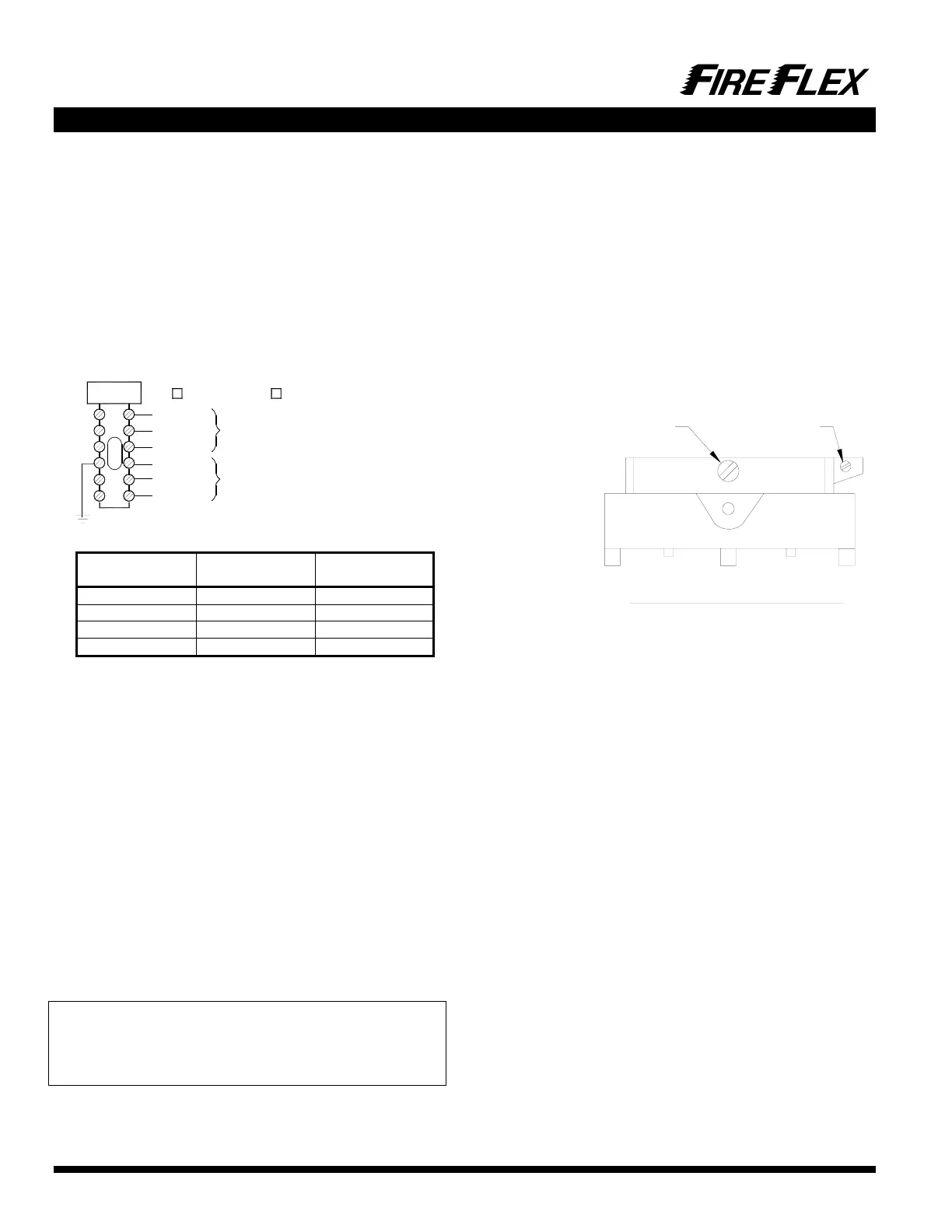
The air compressor cut-off pressure switch (E2) (shown
below with its metal cover removed) has its air
compressor cut-out adjustment switch (middle screw)
factory set. This switch should not need any adjustment
but if necessary, follow the instructions below:
.a Remove the metal cover of the compressor air
pressure switch (E2).
.b To raise the cut-out pressure of the air compressor,
turn the cut-out adjustment screw (middle) half a turn
CLOCKWISE.
.c Open the system main drain valve (D3) and let the
pressure drop until the air compressor (E1) restarts.
Check pressure reading on the system pressure
gauge (E3) when the air compressor stops again.
Repeat until the desired pressure is reached. Once all
done, replace the metal cover on the switch (E2).
Turn clockwise to increase
both cut-out and cut-in
pressure adjustment.
Factory set.
DO NOT CHANGE !
Front view of the Furnass Switch
(Part # 69HA3)
FM-072Q-0-109 A
Note: Do not turn the cut-out adjustment screw (middle) all
the way down in one shot. Proceed by steps. Use the
same method turning the cut-out adjustment screw
COUNTER-CLOCKWISE to lower the air compressor cut-
out pressure.
Air options "B" or "C":
.4 To Apply Air Supply:
Turn on upstream air supply. Open APMD (Air Pressure
Maintenance Device) input valve (E6) by placing handle
in line with valve body then open APMD output
valve (E7) by placing handle in line with the valve body.
In order to accelerate filling of sprinkler piping by air
pressure, bypass valve (E8) can be opened by placing
handle in line with valve body while piping is initially filled
by the air compressor,. This valve (E8) must then be
closed (handle crossways to valve body) and kept in this
position once the system is filled with air.
.5 To Close Air Supply:
Close APMD output valve (E7) by placing handle
crossways to valve body then close APMD input
valve (E6) by also placing handle crossways to the valve
body. Be sure bypass valve (E8) is closed (handle
crossways to valve body).
.6 To Adjust System Air pressure:
Be sure APMD input valve (E6) and APMD output
valve (E7) are both open (handle in line with the valve
body), and bypass valve (E8) is closed (handle crossways
to valve body) prior to performing this operation. Loosen
lock nut and turn pressure adjustment nut clockwise to
 Loading...

