REV. 10-18-19 Page 2
PAVER-CP-MT/ PAVER-CP-MSI
DESCRIPTION: The Paver Kit face plate bracket (control panel) is designed to install in conjunction with a typical paver
block re pit kit (purchased separately). It installs underneath the re pit pan/disc in place of one patio block. The control
panel itself provides a convenient location to house the gas valve and Piezo ignition (if applicable) then is easily removed
for servicing.
This installation instruction covers two (2) separate kits: 1) PAVER-CP-MT and 2) PAVER-CP-MT-MSI.
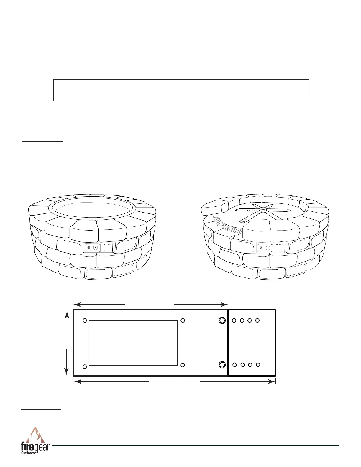
DIMENSIONS: The Paver Kit bracket and extension will t an opening with a maximum of 10½” wide x 3½” tall. Without
the Bracket Extension plate the maximum width is 8” wide. The holes in the Extension Bracket are spaced every ½”.
10½” Max.
8.00” Min.
3½”
Fig 3. Paver Kit Control Panel Dimensions
Fig. 1 Paver kit with re pit pan. Fig. 2. Paver kit with re pit at disc with ex frame.
TOOLS NEEDED: (1) Drill/driver, Gas Rated Teon Tape or Compound, 5/16” Hex head driver, (1) 3/16” Concrete Drill
Bit, (2) Adjustable Wrenches, Assorted Open-end Wrenches
PRECAUTION: If you are installing the MSI (Manual Spark Ignition) ensure the PAVER-CP-MT-MSI control panel is
within 40-inches of the 2-probe Piezo ignitor. This will allow enough “play” in the wires to make your connections. See
Fig. 19 on page 7.
Round Fire Pit Pan
Note: Stainless steel parts have plastic lm to protect the surface on
one side. PEEL the plastic coating off each part before installing.
Table of Contents
Description Page 2
General Instructions Page 2-3
PAVER-CP-MT Page 3-5
PAVER-CP-MSI Page 5-8
Warranty Page 8
Replacement Parts Page 9
 Loading...