REV. 10-18-19 Page 4
PAVER-CP-MT/ PAVER-CP-MSI
Paver Block
Fig. 7 Installing MT valve into control panel.
STEP 2: Once the 90° elbows are installed into the manual
key valve then install the MT key valve bracket into Paver
Kit control panel as shown in Fig. 7.
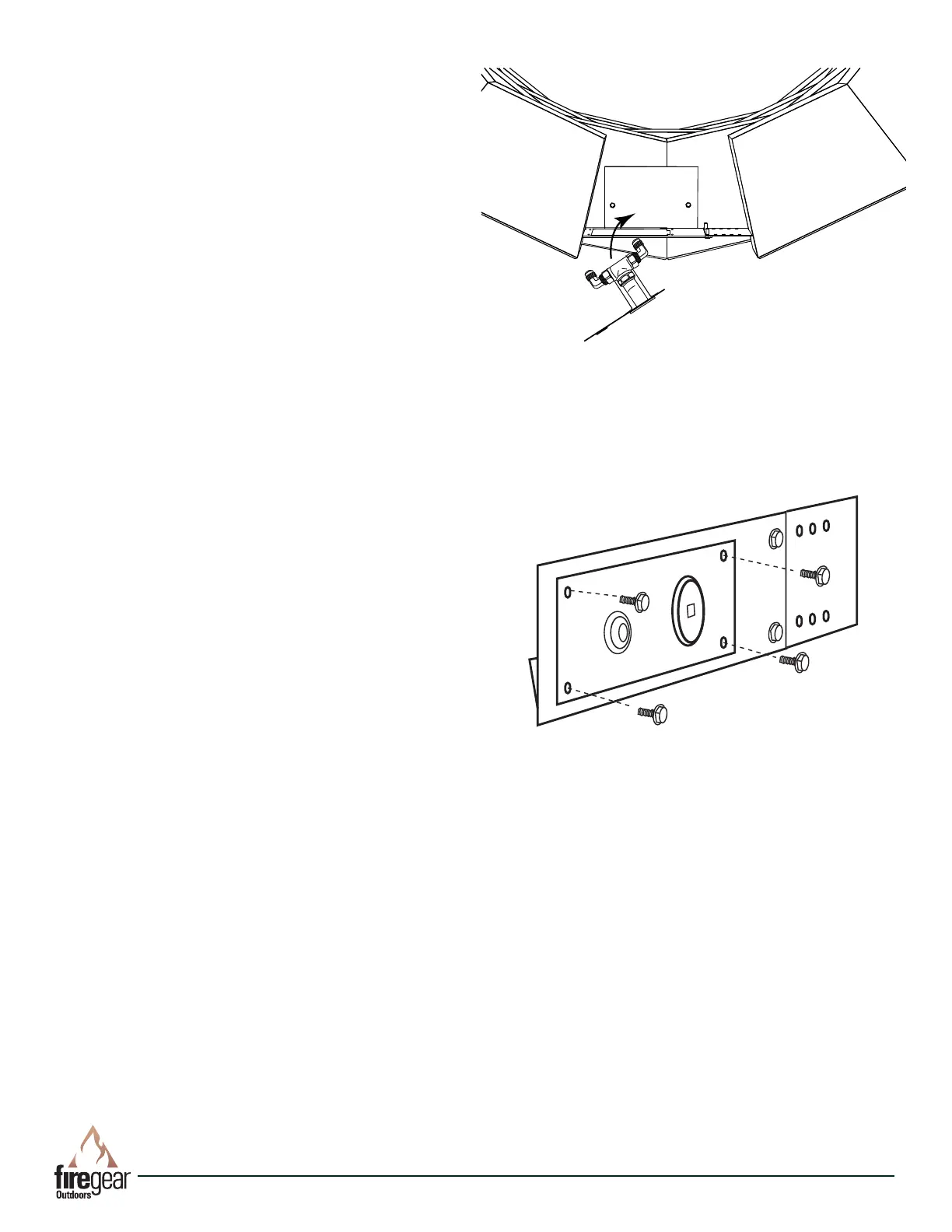
STEP 3: Secure the key valve bracket into place using the
four black thread cutting screws (See Fig. 8).
STEP 4: Install the ex connector from the burner to either
side of the gas valve and connect gas supply to the other
side of the gas valve. Conduct a trial burn test by tempo-
rarily connecting the re pit pan and burner and check for
any gas leaks before completing the installation. See re pit
manual for proper connections.
See page 5 for lighting instructions.
STEP 5: After burn test is complete, nish the patio paver
blocks installation.
Fig. 8 Close up view securing MT valve bracket to control
panel.