EasyManua.ls Logo

Firehawk FHB10W - User Manual

Firehawk FHB10W
2 pages
Print Icon
To Next Page IconTo Next Page
Loading...
PLEASE read all instructions BEFORE beginning to pair a system!
1.0 Plug alarm into pattress and switch on radio
base, the pattress led will flash green twice per
second. If not please complete step 6.0
2.0 Bring alarm & radio base together then twist/slide to lock into place.
3.1 Group the alarms on the right hand side of your
table, then place two alarms in front of you spaced
approximately 20cm APART.
3.2 Press the TEST BUTTON on one alarm and wait
THREE SECONDS.
3.3 Press the TEST BUTTON on the other alarm.
3.4 Watch carefully as both alarms FLASH GREEN
AND RED
3.5 As soon as one FLASHES GREEN ONLY, move it to the left of the table.
3.6 The other alarm will continue to FLASH GREEN AND RED until it BEEPS ,then it will
FLASH GREEN (CO
x4) THE TWO ALARMS ARE NOW PAIRED.
3.7 There is now a 10 SECOND WINDOW to allow another device to be added to the system
If no other devices are to be added proceed to Step 5.0
Connect and assemble all of the alarms in your system before starting the pairing process.
Wait for smoke or heat alarm to BEEP
TWICE Wait for the CO alarm to BEEP
FOUR TIMES
1
CONNECT
2
ALARM ASSEMBLY
3
PAIRING TWO ALARMS
SMOKE ALARM FHB10W HEAT ALARM FHH10W CO ALARM CO7B (10Y)W
20cm
PAIRED
PRESS
& WAIT
FOR 3
SECS.
3.1 3.2 3.3 3.4 3.5
3.2 3.3
PAIRED
20cm
UNPAIRED
ALARM(S)
Pairing Radio Linked Alarms Instructions
Question and Answer IconNeed help?

Do you have a question about the Firehawk FHB10W and is the answer not in the manual?

Overview

This document outlines the instructions for pairing Firehawk radio-linked alarms, including smoke, heat, and CO alarms. The process is divided into several key stages: connecting the alarm, assembling the alarm, pairing two alarms, pairing additional alarms, preparing paired alarms for installation, and resetting the device.

Connecting the Alarm

The initial step involves connecting the alarm to its power source. Users are instructed to plug the alarm into a pattress and switch on the radio base. Upon successful connection, the LED on the pattress should flash green twice per second. If this does not occur, users are directed to proceed to step 6.0, which covers device reset. This ensures that the alarm is properly powered and ready for the subsequent pairing process.

Alarm Assembly

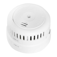
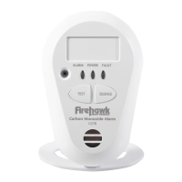
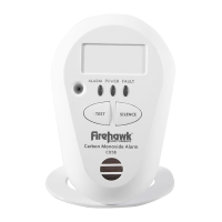
Once connected, the alarm and its radio base need to be assembled. The instructions specify bringing the alarm and radio base together, then twisting or sliding them to lock into place. This physical assembly ensures the components are securely joined. After assembly, the alarms provide auditory cues to indicate their readiness for pairing: smoke or heat alarms will beep twice, while CO alarms will beep four times. It is crucial to connect and assemble all alarms in the system before initiating the pairing process to ensure a smooth and continuous setup.

Pairing Two Alarms

This section details the core process of linking two alarms together.

  • Initial Setup: Users are advised to group all alarms on the right side of their table and then place two alarms in front of them, spaced approximately 20cm apart. This specific arrangement helps in managing the pairing process effectively.
  • First Alarm Activation: The first step in pairing involves pressing the TEST BUTTON on one of the alarms and waiting for three seconds. This action initiates the pairing mode for that specific alarm.
  • Second Alarm Activation: Immediately after activating the first alarm, users must press the TEST BUTTON on the other alarm. This signals the second alarm to enter pairing mode and attempt to connect with the first.
  • Visual Confirmation of Pairing Attempt: As the alarms attempt to pair, both alarms will flash green and red. This visual cue indicates that they are actively trying to establish a connection.
  • Identifying the Paired Alarm: Users are instructed to watch carefully. As soon as one alarm flashes green only, it signifies that this alarm has successfully paired and is now considered the "paired alarm." This alarm should then be moved to the left side of the table, separating it from the remaining unpaired alarms.
  • Confirmation of Successful Pairing: The other alarm, which is still flashing green and red, will continue to do so until it beeps. After beeping, it will flash green (or four times for CO alarms), indicating that it has also successfully paired. At this point, the two alarms are officially paired.
  • Time Window for Additional Devices: Following successful pairing, there is a 10-second window during which another device can be added to the system. If no further devices are to be added, users should proceed to step 5.0. This time-sensitive window is critical for efficiently expanding the alarm system.

Pairing Additional Alarms

This section explains how to expand the system by adding more alarms after the initial two have been paired.

  • Setup for Additional Alarms: To add more alarms, users should place the alarm that previously beeped (the "paired alarm" from section 3.6) approximately 20cm apart from an "assembled alarm" (an unpaired alarm that has been connected and assembled as per point 2.0). This maintains the 20cm spacing for optimal pairing.
  • Activating the Paired Alarm: Users must press the TEST BUTTON on the paired alarm (the one that beeped) and wait for three seconds. This re-activates its pairing mode, allowing it to connect with a new device.
  • Activating the Unpaired Alarm: Next, users press the TEST BUTTON on the unpaired alarm. This initiates its attempt to connect with the paired alarm.
  • Repeating the Process: Steps 3.4 to 3.6, which involve watching for flashing lights, identifying the paired alarm, and confirming the beep, should be repeated until all desired alarms have been added to the system.
  • Important Tip: A crucial tip provided is to "always pair from the PAIRED ALARM THAT BEEPED." This ensures consistency and efficiency in the pairing process, as any of the previously paired alarms can serve as the starting point for adding new ones.

Paired Alarms Ready for Installation

This stage prepares the alarms for final installation and verifies their successful pairing.

  • Allowing the Window to Elapse: If no more alarms are to be added, users should allow the 10-second window (mentioned in step 3.7) to elapse. During this time, each device should continue to flash green, indicating its readiness.
  • Final Pairing Confirmation: To complete the pairing process, each alarm will beep and flash green. This serves as the final confirmation that all alarms are successfully paired and ready for deployment.
  • Troubleshooting Failed Pairing: If any device fails to beep and instead flashes red, it indicates a pairing failure. In such cases, users are instructed to reset all devices and repeat the entire pairing process from the beginning. This ensures that all alarms are properly linked before installation.
  • Testing Paired Alarms: Users are advised to press the TEST BUTTON on one alarm and wait for each paired alarm to sound. It is noted that due to signal timings, an alarm might not sound during this initial test, which does not necessarily indicate a connection problem. To confirm proper functionality, users must perform a test from the said alarm, as well as from each alarm in the system, to ensure that all alarms are paired and communicating effectively.
  • Important Tip: A common mistake highlighted is "missing the 10 SECOND window" during the pairing process. This emphasizes the importance of adhering to the time-sensitive steps. After successful pairing, users are instructed to install their alarms around their home and then test them again with the alarms in their final positions to confirm proper operation in the intended environment.

Device Reset

This section provides instructions for resetting the alarm device to its factory settings, which is useful for troubleshooting or reconfiguring the system.

  • Resetting the Pattress: To reset the pattress, users must first remove the alarm device from it. Once removed, they should press the black button located on the pattress. This action will restore factory settings and unlearn all previously paired devices.
  • Visual Confirmation of Reset: After pressing the button, the LED will flash red four times, then begin to flash green as described in step 1.0. This visual sequence confirms that the device has been successfully reset.
  • Restarting the Pairing Process: Following a reset, users are instructed to start again and repeat the entire pairing process from the beginning. This ensures a fresh start for pairing and resolves any previous configuration issues.

General Usage and Maintenance Features:

  • Radio-Linked System: The alarms are designed to be radio-linked, meaning they communicate wirelessly with each other. This feature allows for a comprehensive safety system where if one alarm detects an issue, all linked alarms will sound, providing earlier warning throughout the property.
  • Auditory and Visual Cues: The system relies heavily on both auditory (beeps) and visual (flashing LEDs in green and red) cues to guide users through the pairing process and indicate the status of the alarms. This multi-modal feedback helps users understand the state of their devices at each step.
  • Modular System: The ability to pair additional alarms allows users to expand their safety system as needed, covering multiple rooms or larger properties.
  • Troubleshooting Guidance: The manual provides clear instructions for troubleshooting, particularly when pairing fails, directing users to reset devices and restart the process.
  • Pre-Installation Testing: The emphasis on testing alarms both immediately after pairing and again after installation highlights the importance of verifying the system's functionality in its operational environment.
  • Clear Step-by-Step Instructions: The instructions are broken down into numbered steps with accompanying diagrams, making the pairing process easy to follow even for users unfamiliar with such devices.
  • Safety Focus: The overall design and instructions prioritize safety by ensuring that alarms are correctly paired and functioning, providing reliable detection of smoke, heat, or carbon monoxide.
  • Manufacturer Information: Contact details for Fireblitz Extinguisher Ltd are provided for customer support, including telephone, fax, email, and website, ensuring users can access assistance if needed.
  • Design Flexibility: The manufacturer reserves the right to change design or specification details without prior notice, indicating ongoing product development and improvement.

Firehawk FHB10W Specifications

General IconGeneral
BrandFirehawk
ModelFHB10W
CategoryCarbon Monoxide Alarm
LanguageEnglish

Related product manuals