Guidelines about the wiring connections to the FirePro Aerosol Generators
FP-20SE/T/TH, FP-40S/T, FP-80S/T,FP-100S, FP-200S,FP-500S.
Step 1: Open the package and take one Aerosol Generator unit.
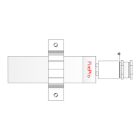
Step 2: Disconnect the moving parts of the aerosol generator and separate the 3 units.
Unit 1: Cable gland fixing component.
Unit 2: Cable gland & Activator cable housing.
Unit 3: Generator.
Step 3: Prepare the cable / wires with the correct size.
“This is very important” please be sure that you follow correctly the below step by
step procedure:
Step 3.1: Mark the cable 6.5 cm from the edge. Point (A).
Step 3.2: Mark 3 cm from point (A) to point (B). Remove the shield of the cable from
point (B) to the edge of the cable.
Step 3.3: Cut the positive wire ( + ) and negative wire ( - ) 1.5 cm from
point (B) to point (C).
Step 3.4: Clean the edges of the positive wire ( + ) and negative wire ( - )
4mm approximately. From point (C) to point (D).
Step 3.5: Slice the shield of the cable from point (B) to point (A).
Step 3.6: Take out the earth wire.
Step 3.7: Cable is ready to be used.
Step 4: Pass the prepared cable through the UNIT 1 (Cable gland fixing component) and
through the UNIT 2 (Cable gland & Activator cable housing).
DO NOT PASS THE EARTH WIRE.
Step 5: Connect the cable wires, positive ( + ) & negative ( - ), with the aerosol unit connector
with any of the 2 non polarized activator cables.
Step 6: Pull back the cable until the edge of the cable shield just shown.
Step 7: Hold the cable avoiding the turning of the connector within housing while turning by
hand the activator cable housing (part 1) with activator cable housing (part 2).
Step 8: Put silicon within the gland around cable in order to seal it.
Step 9: By using two spanner keys connect Unit 1 (cable gland fixing component) with Unit 2
(Cable gland & Activator cable).
Step 10: Connect earth wire with earth tag.
Step 11: Seal with silicone the cut shielded cable and the entrance of the cable into the Unit
1 (cable gland fixing component).
 Loading...