ELECTRICAL SPECIFICATION (at 24VDC supply unless otherwise stated):
8.5mA Typ (excluding external load currents)
16mA Typ (excluding external load currents)
Maximum Alarm Current
Draw
100mA (excluding external load currents)
3A (including extinguisher operate current)
1A to 4A depending on voltage and number of
suppressors (StatX = 1.8 Ohms nominal each unit)
Up to 2 units on 12V, 4 units max on 24V
Connect in series with bi-directional catch diodes
across each element (see manual).
Output is Vin via switch with 6 Ohms in series.
Constant I2T limit = 9 Amp2*Seconds
<4mA, Fault if loop R>300, 12Vmax o/c voltage
Norm S/C, >1K active typ.
12VDC regulated, filtered and transient protected
Alarm condition threshold
Fault condition threshold
Open circuit or ground fault = fault indication
2A @ VinDC (Vin thru NO relay circuit)
Relay Contacts (volt free)
2A @ 24VDC (relay changeover circuit)
75mm diameter round hole, retained by four #6*25
self tapping screws
Via 3 * 6 way terminal block accepting <1mm
2
wires with ferrules
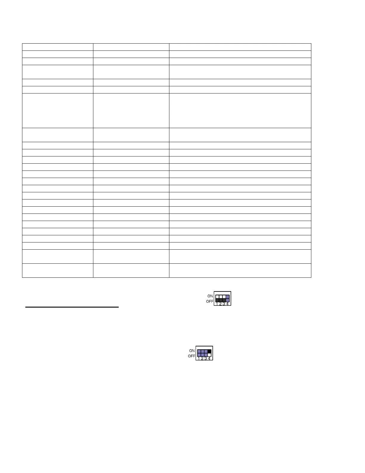
DIP SWITCH SETTINGS (Black = switch tab)
DIP switches 1.2.3 set a delay time between shutdown (VFC) and subsequent
extinguisher automatic activation. Delay can be set 0 to 30 seconds in 5 second steps.
Manual only mode can be set with ON.ON.ON.OPT
DIP switch 4 defines critical alarm OPTion.
The default setting is OFF which requires 2 loops to be in alarm (OPT=“double knock”)
before shutdown and time delayed extinguisher activation.
Moving to ON position requires only one loop to be in alarm (OPT=“single knock”)
before shutdown and time delayed extinguisher activation.
Note that the unit dispenses activation delay following depowering of ignition input.
The instant mode is indicated by flashing green PWR LED which gives double flash
whilst moving through the delay and single flash on reaching zero delay instant mode.
 Loading...