BACK OF
GAUGE
RING
CONNECTOR
(TO GROUND)
POSITIVE WIRE
(TO DASHBOARD
ILLUMINATION WIRE)
S
TEP
7 - R
OUTE
THE
ELECTRICAL
WIRE
Install the relay within three feet of the compressor. Nylon ties
can be used to secure any excess wire and the relay neatly into
place. Route the white wire labeled “Switch Panel” to the control
panel. Connect the white wire to one of the white wires on the back
of the switch. The remaining white wire will be grounded to the
vehicle. Next, connect the orange wire labeled “Comp +” to the red
(positive) wire on the compressor. Connect the red, fused wire
labeled "Bat +" from the relay to the battery or another 12V (posi-
tive) source capable of supporting 20 amps. See Figure "A".
S
TEP
8 - W
IRE
THE
CONTROL
PANEL
FOR
ILLUMINATION
There are two wires on the back of the gauge; Connect the one wire
to a fused dashboard illumination wire. Connect the other wire to a
suitable ground source see Figure "F".
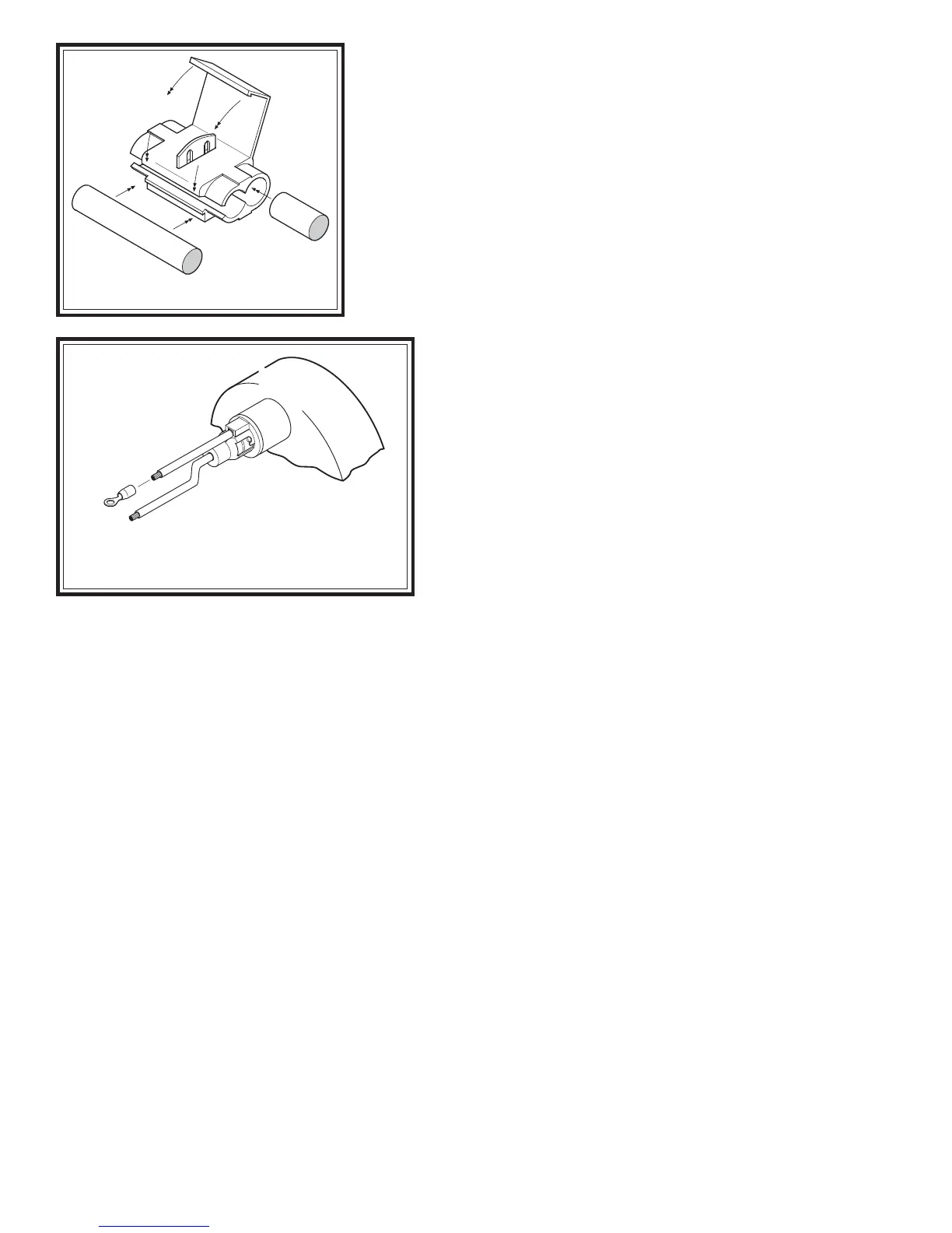
Attach the end of the positive wire to a dashboard
illumination wire using a wire connector. Slip the wire
connector over the existing dashboard illumination wire and
insert the un-stripped gauge panel wire into the wire connector.
Close the wire connector over the wires with pliers, see
Figure "E". Attach the other wire to a ground source by
crimping a ring connector on to the wire and securing it to a
suitable ground source on the vehicle. Note: Should
additional wire be necessary to reach the dashboard
illumination wire and ground source, use 16 gage multi-
strand wire.
S
TEP
9 - C
HECK
THE
SYSTEM
With the Level Command kit and your air helper springs
installed, you are ready to test the system. Reattach the
negative battery cable. Turn on the vehicle's ignition. Push
the paddle switch up to inflate the air springs. The gauge will display how much air pressure is in the air springs. Inflate
the air helper springs to 70 psi OR the max operating pressure for the air springs, whichever is less, and check the fittings
for air leaks with an applied solution of soap and water. If a leak is detected at a tubing connection, check to make
sure that the tube is cut as square as possible and that it is pushed completely into the fitting. The tubing can easily be
removed from the fitting. First, release the pressure from the air spring. Push the collar towards the body of the fitting
and pull out the tube.
Note: If it is necessary to remove the air line from one of the barbed fittings, use a shaving motion with a sharp knife
to shave the air line until it is thin enough to pull off of the barbed fitting. DO NOT cut, scrape, or damage the fitting
or it may cause a leak path.
NOTE: If the system inflates the air springs normally but only releases the air pressure in the line and not
the air springs, the air lines are not properly installed on the switch and gauge. Switch the air lines making sure
the line from the air spring is connected to the gauge, and the line from the compressor is connected to the "SUP"
fitting on the switch.
SYSTEM OPERATION
The Level Command kit allows the air springs to be inflated from the inside of the vehicle. Push the paddle switch
up to inflate the air springs and push the paddle switch down to deflate the air springs.
Figure "E"
Figure "F"
WIRE FROM
PANEL LIGHT
CONNECTING WIRE
PLASTIC
CONNECTOR

 Loading...