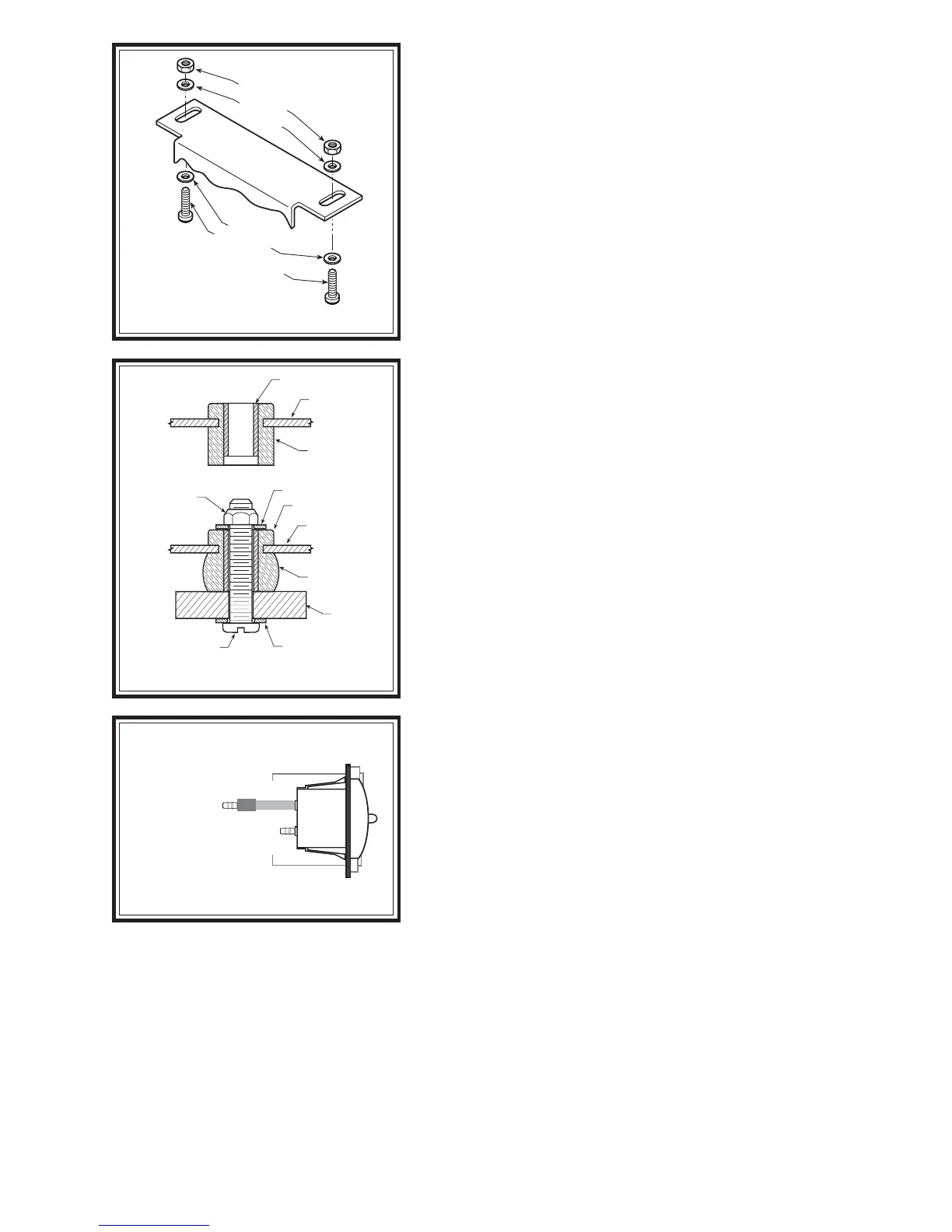
LOCK NUTS
WASHERS
MACHINE SREWS
CONTROL PANEL
BRACKET
WASHERS
S
TEP
1 - S
ELECT
A
MOUNTING
LOCATION
FOR
THE
CONTROL
PANEL
Select a mounting surface under the dashboard or other protected
location. Using the control panel as a template, mark each of the
mounting points with a center punch. Drill a 3/16" diameter hole on each
center mark see Figure "B". Do not attach the control panel at this
time.
S
TEP
2 - P
REPARE
THE
COMPRESSOR
Install the push-to-connect male fitting into the check valve on the
compressor head see Figure "A". Tighten the fitting sufficiently to
engage at least two threads with pre-applied orange thread sealant. DO
NOT OVERTIGHTEN THE FITTING.
S
TEP
3 - M
OUNT
THE
COMPRESSOR
Begin by removing the negative battery cable. Select a convenient
location to mount the compressor. This location should provide ample air
flow and be protected from airborne debris and moisture. The mounting
surface should be rigid to support the compressor, such as under the hood
on a fender well or in a vented storage compartment. The compressor
is oil-less and can be mounted in any orientation necessary for installation.
Using the compressor as a template and a center punch, mark and drill
four 3/16" holes. Any burrs in the holes should be removed to prevent
damage to the rubber isolators. Mount the compressor using the supplied
10 -32 x 1" machine screws, 10 -32 lock nuts, and 3/16" washers see
Figure "C". Maximum vibration isolation can be achieved by properly
mounting the compressor. The machine screw and nut should be
tightened only enough to bottom-out the brass insert see Figure "C".
DO NOT OVERTIGHTEN. Overtightening will crush the brass insert
and the rubber isolator, thereby reducing vibration isolation. Finally,
connect the black wire with the ring terminal from the compressor to a
suitable ground.
S
TEP
4 - R
OUTE
THE
AIR
LINE
Before installing the air line tubing, ensure that there is no pressure
in the air springs. To release the air pressure, remove the valve core from
the manual inflation valves or release the pressure by using a tire gauge
to depress the valve stem.
A) C
OMPRESSOR
TO
CONTROL
PANEL
Cut a piece of air line tubing that will reach from the control panel to
the compressor. Cut the air line tubing as squarely as possible and install
the tubing on to the barbed fitting on the back of the switch marked SUP
(supply) see Figures "A" & "D". Before attaching the air line tubing
to the control panel, soak the end (1") of the air line in hot water for a few
minutes to soften the tubing. Do not use pliers to work the tubing on to
the barbed fitting, as the tubing may be damaged. It may be necessary
to drill a hole in the firewall to route the tubing. Do not fold or kink the
tubing. Ensure that the tubing is protected from sharp edges when
passing through the firewall.
B) C
ONTROL
PANEL
TO
AIR
SPRINGS
Cut a length of air line tubing that will reach from the control panel to the rear of the vehicle. Slide the tubing as
far as possible onto the barbed fitting on the back of the gauge, see Figures "A" & "D". Do not use pliers to work
the tubing on to the barbed fitting, as the tubing may be damaged. Install a T-fitting on the opposite end of the tubing
at the rear of the vehicle. Route a length of air line tubing from the T-fitting to each air spring. Use the suppled nylon
ties to secure the tubing to the vehicle. Make sure that the tubing is protected from sharp edges when passing through
the firewall.
STEP
6 - ATTACH
THE
CONTROL
PANEL
TO
THE
DASHBOARD
Place the air control panel on the dash where the holes were drilled in Step 1. Using the provided machine screws,
lock nuts, and washers attach the air control panel to the dashboard or selected mounting surface see Figure "B".
Figure "B"
Figure "C"
Figure "D"
BRASS SLEEVE
COMPRESSOR
FOOT
RUBBER
ISOLATOR
BRASS SLEEVE
COMPRESSOR
FOOT
RUBBER
ISOLATOR
#10 FLAT WASHER
#10 FLAT WASHER
VEHICLE
MOUNTING
SURFACE
#10 -32 LOCK
NUT
#10-32 x 1 PAN HEAD
SCREW
SIDE VIEW OF CONTROL PANEL
SUP
DEL
TO AIR SPRINGS
BARB FITTING
FROM COMPRESSOR

 Loading...