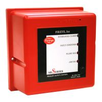
The Fireye SBSeries Flame Safeguard Control is a compact, microprocessor-based, modular burner management system designed for automatic ignition and continuous flame monitoring in commercial heating and process equipment. It is capable of firing any type of fuel and is tested to EN298 standards.
Function Description
The control unit integrates all necessary digital logic and analog measuring circuitry to manage the sequence and monitor the flame of single gas, oil, or combination gas/oil burners. It offers three available control sequences: no-purge, purge, and modulation (which includes air damper control). The specific part number of the unit determines its features, such as the flame sensor type, purge options, modulation capabilities, proof of air opening at start, and various timings. This design ensures control and protection against unauthorized tampering of critical sequences.
The SBSeries supports various flame sensors, including flame rods (rectified ionization), ultra-violet (UV) scanners, and self-checking UV scanners for continuous operation. Four types of non-self-checking UV scanners are available to meet diverse environmental conditions.
Usage Features
The SBSeries units feature LED indicators on the front panel that display the current operating status of the burner system, including a lockout alarm. A recessed test jack on the front cover allows for real-time readings from the connected flame sensor. This test jack also serves as a connection point for an alpha-numeric display, the SB20896. A push button on the unit provides a reset function from a lockout condition and can place the unit in a check condition for pilot turn-down tests.
The SBSeries flame safeguard control family is designed for plug-in installation and is available in models that operate at 120 VAC or 230 VAC, at 50/60 Hz, ensuring universal compatibility.
The wiring base facilitates convenient connection of field wiring from the burner and valve system to the control unit. Three styles of bases are available: an internal terminal base with a guarded wiring compartment, an external terminal base for use within a protective control panel, and an expanded external terminal base for modulation sequence control units.
Installation Guidelines:
- Wiring Base: The wiring base should be mounted on the burner or a panel in a location free from excessive vibration and within the specified ambient temperature range. It can be mounted in any angular position. All wiring must comply with applicable electrical codes, regulations, and local ordinances, using moisture-resistant wire suitable for at least 90°C. A robust ground system is crucial to minimize AC quality problems like spikes, surges, and impulses, ensuring a low impedance path to ground and preventing damage.
- Terminal 7 - Interlocks and Limit Switch Input: External interlock, control, and limit switches are wired in series to this input. Care must be taken to guard against induced voltage levels, which may require a load (relay or light) to prevent system error lockouts in long wiring runs. This input powers the valve and ignition output terminals, so all connected switches must handle the total current required by terminals 3, 4, and 5. Electronic limit switches should be avoided as they can cause erratic operation.
- Terminal 6 - Combustion Air Switch Input: For purge and modulation models, switches and contacts for proving airflow are wired in series to this terminal. Power must not be present at terminal 6 when power is first applied to terminals 1 or 7. If the combustion air blower is controlled externally, a three-way solenoid valve must connect the air switch port to the blower sensing port, venting the switch to ambient when de-energized.
- Terminal 4 - Ignition Wiring: The output terminal typically powers a high voltage transformer. High voltage ignition wiring should be routed sufficiently far from all sensors and other low voltage wiring to prevent electrical interference. The high voltage wire should be as short as possible, ideally with the ignition transformer mounted close to the burner and a low impedance path from burner ground to transformer ground. Avoid creating a loop antenna around the SBSeries and sensor wiring.
- Low Fire Start Switch (Terminal 3 – resistance through valve coil): For modulation sequence models, this feature allows wiring the system to check the low fire start position before pilot ignition. The low fire start switch must connect between terminal 3 and the pilot valve. For direct spark burners, a bypass contact is needed around the low fire switch.
- Main Valve Closed Switch Input (Terminal V or D): The system can be wired to check the main valve closed switch on the main gas valve before start-up and after the burner cycle. For purge and no-purge models, the main valve closed switch connects to Terminal V, and a jumper in the base must be cut. For modulation models, the main valve closed switch is wired in series between the airflow switch and the high purge damper switch, requiring the jumper in the base to be cut.
- High Purge Switch Input (Terminal D): For modulation models, the system can check the high purge position for the high fire purge portion of the sequence. This requires cutting the red jumper in the base and connecting the high purge position switch from terminal D. If not used, the jumper remains intact, and a jumper must be installed between terminals 1 and D.
- Terminal 1 - Remote Reset: This feature allows remote mounting of a switch to reset the SBSeries. A normally closed remote reset switch must be wired to momentarily interrupt power to terminal 1 when pressed, resetting the SBSeries.
- Remote Display (SB20896): The remote display is mounted through a DIN cutout using supplied brackets. It should be located to minimize electrical interference. Applying and disconnecting display power should coincide with power to terminal 1 of the SBSeries. The appropriate cable (P/N SB20318) connects to the test jack and the S2 terminal of the SBSeries wiring base. Do not parallel the test jack signal to other devices. LCD display contrast can be adjusted on the back.
- Flame Sensor Wires: Control circuit wires must be 1.5mm (No. 16 AWG) or larger, rated for 90°C (194°F) minimum. Flame sensor wires must be run individually in their own separate conduit; multiple unshielded flame sensor wires cannot be run together. The neutral wire to terminal 2 must be at ground potential.
Operation:
The SBSeries CE offers standard features, optional features, system error and lockout conditions, and LED indicator lights.
- Interlocks and Limit Switch Input (Terminal 7): This input is the normal operation control. Interlocks (pressure/temperature switches) start the burner, while limit switches stop it. They are wired in series; a break in this circuit shuts down the burner without an alarm or lockout.
- Combustion Air Switch Input (Terminal 6): For purge and modulation models, this input monitors the combustion air switch separately. The SBSeries checks if the air flow switch is open before start-up, closed during operation, and open at shutdown. An improperly powered input before fan output energizes causes the system error light to blink; it must de-energize within 30 seconds or the system locks out. After fan output energizes, the air switch must close within 10 seconds, or the system locks out. If the air switch opens during the main firing cycle, the system locks out. With the recycle option and main output operating for at least 35 seconds, the system shuts down and restarts.
- Pre-Purge: For purge models, the sequence delays after the air switch is proven by the specified purge time, then proceeds to trial for ignition. For modulation models, the purge time is doubled: a high fire purge for the specified time, followed by a low fire purge to achieve the starting position. High and low fire purge times are set by dipswitches SW 4 - SW 7.
- Main Fuel Valve Closed Switch (Terminal V): For no-purge and purge models, this interlock checks the main valve closed position before start-up and after shutdown. For modulation models, it checks the low fire start position before light-off.
- Main Fuel Valve Closed / High Fire Purge Check (Terminal D): For modulation models, this feature (enabled by cutting a jumper) checks that the high fire purge position switch and main valve closed switch are both made at the end of the high fire purge.
- Low Fire Start (Terminal 3 – impedance): For modulation models, this checks the low fire start position before light-off.
- Pilot Test Mode: The SBSeries holds the sequence once the pilot flame is established, preventing the main valve (terminal 5) from energizing. This mode is entered by depressing the TEST/RESET button on the front cover, causing the green "INTERLOCKS CLOSED" light to blink. To exit, press the button three times.
- Interrupted or Intermittent Pilot: An interrupted pilot shuts off at a specified time after the main valve energizes. An intermittent pilot (00 time) continues throughout the main flame firing cycle.
- Spark, Pilot Flame & Main Flame Separation: During the trial for ignition (TFI), pilot and ignition outputs are energized. At the end of TFI, the pilot output remains, and ignition de-energizes. After a five-second delay to prove the pilot or start flame, the main gas valve energizes.
- Post Purge: For purge and modulation models, post purge maintains combustion air fan output for a specified time after interlocks and limit switch input open.
Optional Features:
- Recycle Mode ("R" specified): The SBSeries restarts the sequence after flame or air failure. It re-initiates start-up automatically only if the main burner has operated for at least 35 seconds. If the pilot or start flame fails during recycling, the system alarms and locks out. If successful, the system is enabled for another recycle after 35 seconds of main burner operation. It never recycles for pilot or starting flame failure.
- Air Switch Input Hold ("H" specified): For purge and modulation models, the SBSeries holds the sequence indefinitely until the air switch input is made, then resumes normal sequence.
- Manual Reset on Power Outage ("B" specified): The TEST/RESET button must be pressed twice to start the sequence after a power outage. The system error light blinks rapidly, and a remote display shows "PUSH RESET TO START."
- Remote Display: The SB510 remote display operates on 120VAC and has a keypad for reset. It mounts through a panel door and features an LCD in a DIN housing. It connects to the SBSeries via a cable to the flame signal test jack and receives serial communication on each sequence state change. It provides status messages, indicates lockout conditions (with time), and continuously monitors flame signal strength and run time.
System Errors and Lockout Conditions:
- Fault Condition (Red "Fault Condition" LED): Prevents gas ignition. The unit continues its sequence after the error is cleared.
- Lockout Condition: Energizes the alarm output and de-energizes gas valve and ignition outputs. The unit must be reset by pressing the button twice (in the out position).
Immediate lockout conditions include:
- Wiring error causing external voltage on output terminals.
- Welded internal contacts or other SBSeries malfunctions.
- Main fuel valve closed position switch open after cycle shutdown or before start-up (system error light blinks twice, then stays on; fan output terminal 8 energizes).
- Low fire fail (modulation model) – low fire switch open before trial for ignition.
- High fire fail (modulating model) – high fire switch not closed at end of high fire purge.
Lockout conditions (after 30 seconds, system error light blinks ~14 times, then stays on) include:
- Air failure (purge/modulation models) – loss of combustion air during operational cycle (Air Failure LED on).
- Pilot flame fail – loss of flame during trial for pilot ignition (Flame Failure LED on).
- Main flame fail – loss of flame during main burner trial for ignition or run period (recycling not selected) (Flame Failure LED on).
- Flame detected out of sequence (faulty scanner, electrical interference on sensor wiring, flame in burner/line of sight due to gas leak/product fire).
- Air flow switch closed before start-up (purge/modulation models).
All status lights and the TEST/RESET push-button are on the front cover.
- Interlocks Closed (Green LED): Illuminates when operation limits are met. Blinks in test mode.
- Air Failure (Red LED): For purge and modulation models, illuminates when combustion air is lost.
- Fault Condition (Red LED): Illuminates when a system error is detected.
- Flame Failure (Red LED): Illuminates when a pilot or main flame fails.
- Low Fire (Yellow LED): For modulation models, illuminates during the low fire period of the purge cycle.
- High Fire (Red LED): For modulation models, illuminates during the high fire period of the purge cycle.
- Auto (Green LED): For modulation models, illuminates during the automatic period (20 seconds after main valve energizes).
- Test/Reset (Push-button): Activates pilot test mode or resets the SBSeries.
- Flame Signal (Red LED): Located behind the signal test port, illuminates when a flame signal is present. Communication signals from the remote display are superimposed on the flame signal test jack but are negligible during a valid flame ON condition. When flame is off, display communication signals appear prevalent.
Maintenance Features
Preventative maintenance is crucial for a reliable, safe, and efficient system. Burners in severe environments or with frequent operation should be checked more often. Monthly and yearly checklists are provided as average intervals, which may need to be shortened based on environmental conditions or local authority recommendations.
Monthly Checklist:
- Inspect Flame-Sensing Devices: Check for good condition and cleanliness. Clean scanner lenses with a soft, damp cloth to maintain flame signal strength. Wash flame rod electrodes and insulators with soap and water, then rinse and dry thoroughly.
- Test Alarm Systems: Verify proper signals for all alarm systems.
- Check Ignition Spark Electrodes: Inspect and ensure proper gap.
- Test Interlock Sequence: Manually trip each safety interlock during burner operation to confirm that related equipment closes or stops as specified by the manufacturer.
- Test Flame Safeguard: Manually shut off gas to the burner to ensure the control initiates a safety lockout.
Yearly Checklist:
- Test Safety Shut-Off Valves: Perform leak tests for tightness of closure.
- Test Pressure Switch Settings: Check switch movements against pressure settings and compare with actual impulse pressure.
- Visually Check Ignition Cable and Connectors: Inspect for any damage or wear.
- Inspect Burner Components: Ensure the following components are not damaged or distorted:
- The burner nozzle
- The spark plugs
- The flame sensors
- The flame tube or combustion block of the burner
Troubleshooting Procedures:
The manual provides a comprehensive troubleshooting guide for various problems, including:
- Cannot initiate start sequence: Possible causes include the main valve not being closed, the air pressure switch not making contact, high or low gas pressure switches tripped, malfunction of the flame safeguard system, purge cycle not completed, main power off, or no power to the control unit. Solutions involve checking valve switches, air pressure switch adjustments, gas pressure, investigating electrical issues, and verifying switch settings.
- Scrambled messages on remote display: This indicates electrical interference, which can be resolved by checking grounding and separating communication cables.
- "UNSAFE AIR SHORT" message appears on display: Possible causes are an improperly adjusted air switch, the air switch being shorted or wired incorrectly, or a faulty scanner. Solutions include checking air switch settings and wiring, and inspecting the scanner.
- Burner flame fails but no flame failure indication occurs: This could be due to improperly connected sensor wires, electrical interference from other current-carrying wires, or improper grounding. Solutions involve checking wiring diagrams, sensor information, and grounding of the neutral at the control power transformer.
- Voltage reading greater than 15VDC at "Test Point" on SBSeries faceplate: This indicates improper grounding, requiring a check of the neutral grounding at the control power transformer.
Sensor Installation:
- Flame Rods: Flame rods are recommended only for gas burners as soot accumulation on oil burners can cause nuisance shutdowns. They should be kept as short as possible and at least 1/2" (13mm) from any refractory. Position the rod into the side of both pilot and main flames, preferably at a descending angle to minimize drooping. It should extend 1/2" (13mm) into nonluminous flames (e.g., blue flames) or at the edge of partially luminous flames. A burner/flame grounding area at least four times greater than the flame rod area contacting the flame is required. Ignition interference from the spark plug may affect flame signal strength and can be mitigated by reversing ignition transformer primary leads, reducing the spark gap, or adding grounding area.
- Scanners: Use only specified Fireye scanners (SB49600-91, SB49600-90, SB20898, SB49602-91). Position the scanner within 18" (457mm) of the flame. Bushing threads are 1/2" F.N.P.T. for most models, with SB49602-91 having 1" F.N.P.T. threads. Ambient temperature limits vary by scanner model; for higher temperatures, use a Fireye heat insulator (P/N 35-319) and potentially a purge tee. An optional magnifying lens (Fireye P/N 46-185) can increase flame signal strength. Aim scanners at the third of the flame closest to the burner nozzle, viewing the intersection of pilot and main flames. Avoid sighting the ignition spark or its reflections. Do not allow the scanner to detect a pilot flame too small to ignite the main burner.
Minimum Pilot Test:
This critical test must be performed by a trained and qualified burner technician. It involves:
- Manually shutting off the main burner fuel supply (not the pilot).
- Starting the system normally.
- Entering pilot test mode (by pressing the test/reset button).
- Measuring signal strength.
- Reducing pilot fuel until the flame relay drops out, then increasing it until the flame signal is >4 VDC and the flame relay just pulls in. This is the minimum pilot. If this flame is insufficient to light the main burner, realign the sensor.
- Exiting pilot test mode and restarting the normal start-up sequence.
- Smoothly restoring main burner fuel during the main flame trial for ignition. If the main burner doesn't light within five seconds, immediately shut off fuel and realign the sensor.
Pilot Flame Failure Test:
- Manually shut off fuel to both pilot and main burners.
- Place the system in pilot test mode.
- Start the system normally. The controller should lock out (alarm output energized, red "Flame Failure" LED on). If not, identify and correct the false flame signal (e.g., spark pickup, faulty scanner).
Main Flame Failure Test (for Interrupted Pilot Systems):
- Manually shut off fuel to the main burner (not the pilot).
- Start the system normally. This should ignite the pilot and then lock out (alarm output energized, red "Flame Failure" LED on) within 4 seconds after pilot interruption. If not, identify and correct the false flame signal.
Spark Sighting Test:
- Manually shut off fuel to both pilot and main burners.
- Start the system normally.
- Measure the flame signal.
- If the flame signal is >4 VDC for more than three seconds during the trial for ignition, the sensor is picking up a signal from the spark plug. This may not require correction if the ignition transformer is connected to terminal 4.
Limits and Interlock Tests:
Periodically check all interlock and limit switches by manually tripping them during burner operation to ensure they cause the system to shut down. Never operate a system with improper adjustments or faulty interlocks/limit switches; always replace faulty equipment before resuming operation to prevent explosions, injuries, and property damage.