from unit (as measured along the low-voltage wires), use No. 16 AWG color-coded, insulated (35 degrees C minimum) wires.
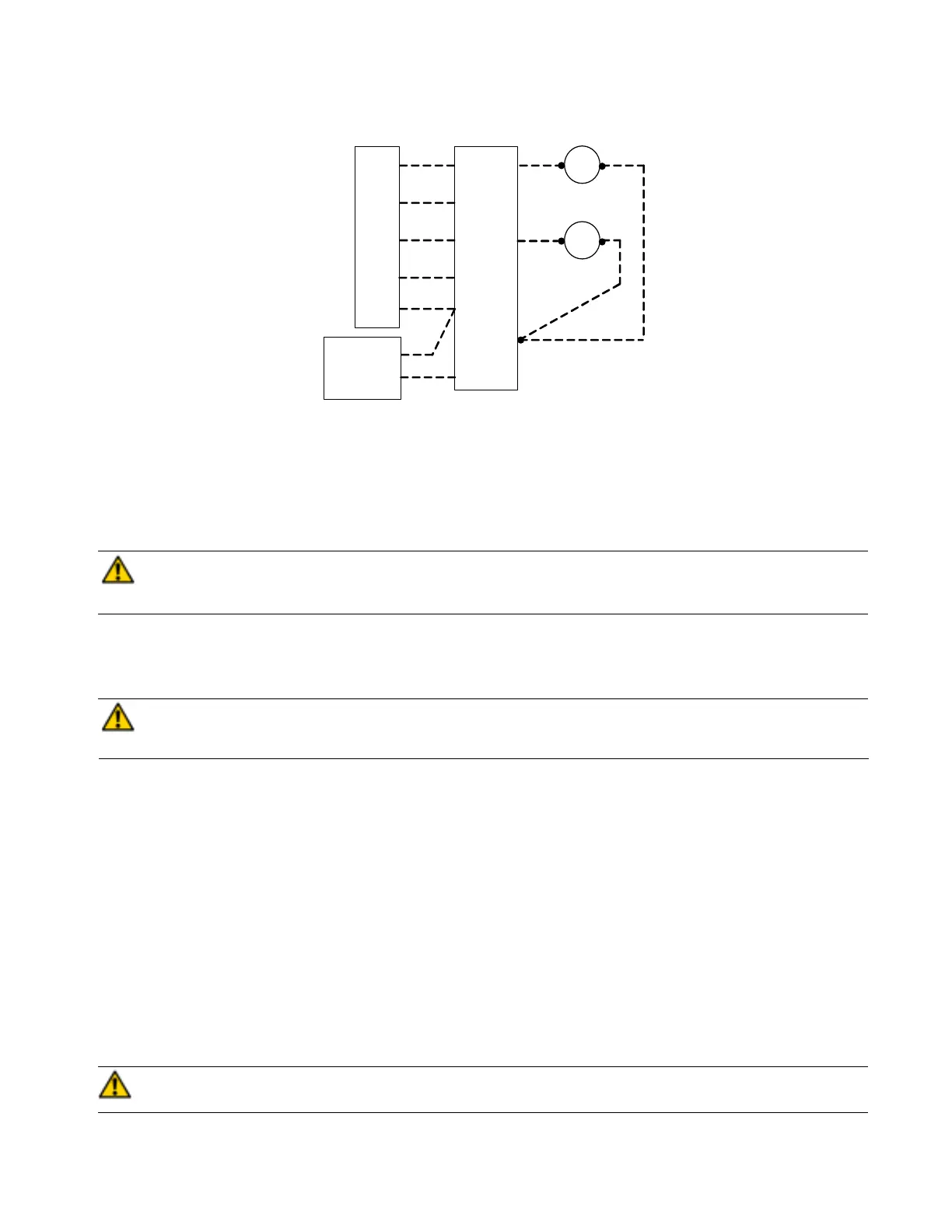
Connect low-voltage thermostat leads and low-voltage outdoor unit leads to the fan coil circuit board as shown on unit
wiring diagram. (See Figure 3.)
CAUTION: Do not use power stealing thermostats. The thermostat will cause the motor to function
improperly. A high grade digital thermostat is recommended. Failure to do so could result in damage to
components and will void all warranties.
These fan coils are provided with a Class 2 transformer for 24volt control circuits. Should any add-on equipment also have
a Class 2 transformer furnished, care must be taken to prevent interconnecting outputs of the two transformers by using a
thermostat with isolating contacts.
CAUTION: Any devices such as fan switches or thermostats that have been furnished by the factory for
field installation must be wired in strict accordance with the wiring diagram that is supplied with the unit.
Failure to do so could result in damage to components and will void all warranties.
PROCEDURE 5 WATER COIL PIPING
Piping Precautions
Flush all field water piping prior to connection to water coils to remove debris.
Use wet cotton rags to cool valve bodies when soldering.
Open all valves (midway for hand valves, manually open on motorized valves) prior to soldering.
When soldering to bronze or brass, heat the piping while in the socket/cup and begin introducing the solder when the flux
boils rapidly. Avoid direct flame into the solder joint.
Heat can only be applied to the cup of the valve body for a minimal time before damage occurs (even with the use of wet
rags.
Avoid rapid quenching of solder joints as this will produce joints of inferior quality.
Connect all piping per accepted industry standards and observe all regulations governing installation of piping systems.
When all connections are complete the system must be pressure tested. Repair any solder joint leaks and gently tighten
any leaking valve packing nuts and piping accessories as required. Hydronic systems are not designed to hold pressurized
air and should only be tested with water.
CAUTION: An expansion tank may be required if a back-flow preventer is installed in the system. Failure to
follow this CAUTION could result in product and property damage.
Figure 3 - Low Voltage Wiring Connections
5
Y1
G
W1
C1
R
NC
HUM
Y
G
W
C
R
DEHUM.
INDOOR
THERMOSTAT
FAN COIL
24V
CONNECTIONS
24V CHILLED
WATER VALVE
CW
24V HOT
WATER VALVE
HW
 Loading...