EasyManua.ls Logo

First Co HBC - User Manual

First Co HBC
11 pages
Print Icon
To Next Page IconTo Next Page
Loading...
IOM4501 Rev. A 06/18 1
HBC(X), PHBC(X), RHBC(X), CHBC(X)
HORIZONTAL HYDRONIC FAN COIL UNITS
Installation, Operation, and
Maintenance Instructions
WARNING TO INSTALLER, SERVICE PERSONNEL, AND OWNER
Altering the product, improper installation, or replacing parts with unauthorized parts voids
all warranty or implied warranty and may result in adverse operational performance or
possible hazardous conditions to service personnel and occupants. Company employees or
contractors are not authorized to waive this warning. Current Maintenance Program is
available HERE.
NOTES: Read the entire installation instruction manual before starting the
installation.
These instructions are intended as a general guide and do not supersede
national, state, or local codes in any way.
These instructions must be left with the property owner.
SAFETY CONSIDERATIONS
Improper installation, adjustment, alteration, service, maintenance, or use can
cause explosion, fire, electrical shock, or other conditions which may cause
personal injury or property damage. Consult a qualified licensed installer,
service agency, or your distributor for information or assistance. The qualified
licensed installer or service agency must use factory-authorized kits or
accessories when modifying this product. Refer to the individual instructions
packaged with kits or accessories when installing.
Follow all safety codes. Wear safety glasses and work gloves. Use quenching
cloth for brazing operations. Have fire extinguisher available. Read these
instructions thoroughly and follow all warnings or cautions attached to the
unit. Consult local building codes and National Electrical Code (NEC) for special
requirements.
Question and Answer IconNeed help?

Do you have a question about the First Co HBC and is the answer not in the manual?

Summary

Installation, Operation, and Maintenance Instructions

WARNING TO INSTALLER, SERVICE PERSONNEL, AND OWNER

General warnings for installers, service personnel, and owners regarding product alteration and installation.

NOTES

Important notes for installers before starting the installation process.

SAFETY CONSIDERATIONS

Safety precautions and guidance for installation, adjustment, alteration, service, and maintenance.

General

Safety Symbol Identification

Explains the general safety-alert symbol and electrical shock hazard symbol.

Warning and Caution Definitions

Defines WARNING for injury/death, CAUTION for damage, and NOTE for suggestions.

General Product and Installation Guidelines

Manufacturer disclaimers, installation rules, and safety practices during construction.

Shipment and Code Compliance

Inspect shipments for damage and adhere to all applicable installation codes.

INSTALLATION PRECAUTIONS

Heavy Unit Handling Warning

Warning about unit weight and need for multiple people to prevent injury or death.

Installation by Licensed Contractor

Emphasizes licensed contractor installation and general precautions.

Essential Installation Practices

Covers tool use, electrical safety, nameplate review, soldering, rotating parts, leveling, drain checks, filter, and air distribution.

FAN COIL UNIT

Installation Code Adherence

Installer must follow all local and national code requirements for installation.

Free Return Installation Guidelines

Guidelines for free return installation, ensuring sealed spaces and proper access.

Drain Pan and Overflow Notes

Notes on secondary drain pans and condensate overflow shut-off switches.

Mounting Requirements

Instructions for securely mounting the fan coils using provided slots and hardware.

AIR DISTRIBUTION DUCTS

Ductwork Installation and Insulation

Ductwork installation must comply with NFPA codes and be adequately insulated.

Duct Sizing and Insulation

Duct systems must be sized correctly and insulated according to standards.

ELECTRICAL

Electrical Shock Hazard Warnings

Critical warnings about electrical shock hazards during servicing and installation.

Wiring Compliance and Diagrams

Field wiring must comply with codes; review wiring diagrams and nameplate data.

Transformer Usage Caution

Units use a Class 2 transformer; avoid interconnecting multiple transformers.

PIPING

Piping Installation Precautions

Precautions for flushing, soldering, supporting pipes, expansion, and valve insulation.

Air Pressure Test Warning

Caution that hydronic systems are tested with water, not air, to prevent damage.

Piping Connection and Sizing

Instructions for piping installation, sizing, and compliance with codes.

Coil Tubing Integrity Caution

Caution against bending coil header tubing to prevent fractures and leaks.

PIPING

External Piping Preparation

Purge external piping of debris before connecting to the fan coil.

Chilled Water Piping Insulation

Chilled water piping requires insulation to prevent condensation damage.

Condensate Drain Line Maintenance

Condensate drain lines need proper slope, traps, and periodic checks for drainage.

Piping Insulation Responsibility

Contractor must insulate lines and valve packages to prevent condensate drippage.

Noise Considerations

Consider noise transfer to the conditioned space from fan coil units.

INSTALLATION OF VALVE CLUSTER ASSEMBLIES

Two-Way Motorized Valve Assembly Installation

Procedure for attaching and installing two-way motorized valve assemblies.

Three-Way Motorized Valve Assembly Installation

Procedure for mounting and installing three-way motorized valve assemblies.

PRE-STARTUP CHECKS

Electrical Grounding and Safety Warnings

Warnings regarding proper electrical grounding and avoiding rotating components.

Thermostat and Switch Wiring Caution

Wire thermostats and switches per diagrams to avoid damage and voiding warranties.

Pre-Startup Unit Checklist

A checklist of essential checks before starting the fan coil unit operation.

MAINTENANCE

Fan Maintenance

Annual inspection and cleaning of the fan for balance and vibration.

Motor Maintenance

Check motor connections for security and adherence to wiring diagrams.

ECM Motor Servicing Warning

Warning for ECM motors: power is always applied, requiring disconnection before servicing.

Filter Maintenance

Air filters require cleaning or replacement every 30 days or more often if conditions require.

Coil Cleaning

Coil heat transfer surfaces must be kept clean using compressed air or water flushing.

Drain Piping Maintenance

Maintenance of drain piping, including slope, disposal point, and periodic checks.

Preventative Maintenance Schedule

Establish and maintain a formal schedule for regular preventative maintenance.

Maintenance Program Updates

Information on obtaining the latest Maintenance Program log.

Overview

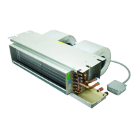
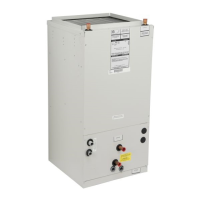
This document provides installation, operation, and maintenance instructions for HBC(X), PHBC(X), RHBC(X), and CHBC(X) Horizontal Hydronic Fan Coil Units.

Function Description:

These units are horizontal hydronic fan coil units designed for indoor installation, typically above a dropped ceiling. They are designed to provide heating and cooling by circulating either hot or chilled water through a hydronic coil. The fan circulates air over the coil, transferring heat to or from the conditioned space. The units are listed for installation with zero clearance to combustible materials, including the fan coil cabinet, discharge plenum, and connecting ducts.

Important Technical Specifications:

  • Installation: Designed for horizontal installation above a dropped ceiling. Indoor use only. Zero clearance to combustible materials.
  • Drainage: Units must be installed level or angled toward the drain nipple to ensure proper drainage. RHBC(X) and CHBC(X) units require a minimum trap of 1-1/2 inches in the drain line. HBC(X) and PHBC(X) units may not require a trapped condensate line if negative pressure is absent, but it is recommended.
  • Electrical: All wiring must comply with local and national codes (e.g., National Electric Code, ANSI/NFPA No. 70). Units are provided with wiring diagrams and nameplate data for field wiring. Remote control boxes may be furnished and should be located near the unit for servicing. Field wiring between the control box and motor junction box must use flexible metal conduit or armored cable. Units include a Class 2 transformer for 24-volt control circuits. Copper conductors only.
  • Piping: Hydronic coil designed for use with hot or chilled water. Piping must be adequately sized for design water flow and installed according to codes. Valve packages will not support the weight of connecting pipes. Provisions for expansion and contraction of piping systems are necessary. Motorized valves must not have the power head below horizontal and require 3/4-inch clearance for removal.
  • Ductwork: All ductwork must comply with National Fire Protection Association Codes 90A and 90B. Ducts should be adequately insulated (minimum 1-inch in conditioned areas, 2-inches in unconditioned areas with a vapor barrier). Return air must be filtered. Supply and return duct systems must be sized for air requirements and static pressure capabilities.

Usage Features:

  • Safety: The manual emphasizes safety with general safety-alert symbols, lightning bolt symbols for electrical shock hazards, and WARNING/CAUTION labels. It warns against altering the product, improper installation, or using unauthorized parts, which voids warranties and can lead to hazardous conditions.
  • Installation Guidance: Detailed instructions are provided for mounting, electrical connections, and piping. It specifies that installation should only be performed by a licensed contractor.
  • Valve Assemblies: The units may use either two-way or three-way motorized valve assemblies. Procedures for attaching these to the coil and ensuring proper operation (e.g., checking hand valve movement, ensuring motorized valve power head is not below horizontal) are outlined.
  • Pre-Startup Checks: A comprehensive list of checks is provided before starting the unit, including verifying supply voltage, proper grounding, blower wheel tightness, secure installation, correct sloping for drainage, accessibility for servicing, proper condensate line setup, sealed cabinet openings, and correct filter installation.

Maintenance Features:

  • Fan Maintenance: The fan should be inspected and cleaned annually to prevent imbalance and vibration.
  • Motor Maintenance: Motor connections should be checked for security according to the wiring diagram. The blower motor should be cleaned annually. For units with ECM motors, power must be disconnected before servicing.
  • Filter Maintenance: The air filter should be cleaned or replaced every 30 days, or more frequently under severe conditions. Always replace with the same type. The unit must never run without an air filter.
  • Coil Cleaning: Dust and contaminants on heat transfer surfaces impair airflow and heat transfer. The coil must be kept clean using low-pressure compressed air or flushing/rinsing with water (detergent advisable for greasy surfaces).
  • Drain Piping Maintenance: The drain line should always be connected to an acceptable disposal point, sloped at least 1/8-inch per foot, and checked before and periodically during summer operation.
  • Preventative Maintenance: A formal schedule of regular maintenance is recommended to achieve maximum performance and service life.
  • Maintenance Program Log: A current copy of the Maintenance Program log is available online at www.firstco.com under "Product Information."

General Warnings and Cautions:

  • Installer/Service Personnel/Owner Responsibility: Altering the product, improper installation, or using unauthorized parts voids warranties and can lead to hazardous conditions. Company employees or contractors are not authorized to waive this warning.
  • Safety First: Always wear eye protection and work gloves. Disconnect all power before servicing. Be aware of multiple disconnect switches. Do not touch rotating components. Secure all panels before operation. Clear the surrounding area of tools and debris.
  • Codes and Regulations: All installations must conform to national, state, and local codes. Local authorities should be consulted.
  • Damage Prevention: Do not operate the unit during building construction due to excessive airborne dust. Do not bend or reposition coil header tubing for alignment. Hydronic systems should only be tested with water, not pressurized air.
  • Noise: While designed for quiet operation, some noise transfer to the conditioned space is expected and should be considered during planning.
  • Warranty: The manufacturer does not warrant equipment subjected to abuse (e.g., metal chips, dust, drywall tape, paint overspray).
  • Shipping Damage: Inspect shipments immediately upon receipt. Note any damage on the delivery receipt and file a claim with the carrier.

First Co HBC Specifications

General IconGeneral
BrandFirst Co
ModelHBC
CategoryHeat Pump
LanguageEnglish