PROCEDURE 6 CONDENSATE DRAIN
Units are equipped with primary and secondary ¾ in. MPT drain connections. For proper condensate line installation see
figure 2. To prevent property damage and achieve optimum drainage performance, both primary and secondary drain lines
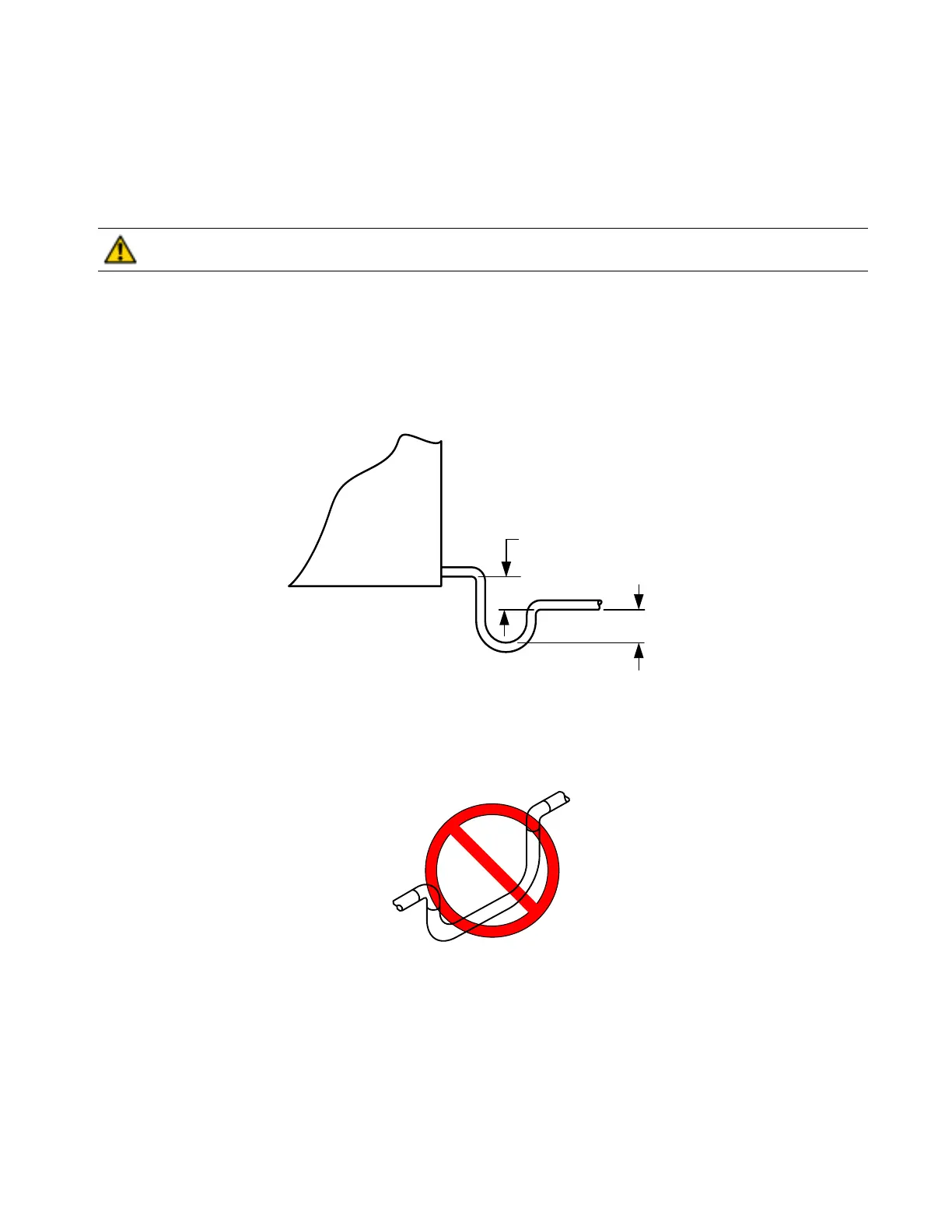
should be installed and include properly-sized condensate traps. (See figure 5 and 7.) Since the drain pan is located on the
suction side of the blower, a negative pressure exists at the drain pan and a minimum trap of 1-1/2 inches must be provided
in the drain line to assure proper drainage.
CAUTION: Shallow running traps are inadequate and DO NOT allow proper condensate drainage. (See
figure 6.) Failure to follow this CAUTION could result in product and property damage.
NOTE: If a Condensate Overflow Shut-off Switch, that is designed to be installed in the drain line, is used in place of a
secondary drain line, then the cut-off switch should be located in the primary drain line between the fan coil unit and the P-trap.
NOTE: When connecting condensate drain lines avoid blocking filter access panel. Prime both primary and secondary
condensate traps after connecting to drain pan.
Figure 5 - Recommended Condensate Trap
DO NOT USE SHALLOW RUNNING TRAPS !
Figure 6 - Insufficient Condensate Trap
1-1/2" MIN
1-1/2" MI
UNIT
 Loading...