PROCEDURE 8 UNIT START-UP
Pre-start Check
Check that supply voltage matches nameplate data.
Ensure that the unit is properly grounded.
With power off, check blower wheel set screw for tightness and ensure that the blower wheel rotates freely and quietly.
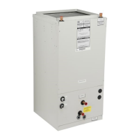
NOTE: Remove the motor blower shipping brace on the 20MB-HW blower assembly. Failure to do so will cause damage to the
unit.
Check that the water coil, valves and piping have been leak checked and insulated as required.
Ensure that all air has been vented from the water coils.
NOTE: It may require purging several gallons of water so have a means of discarding the water.
Install all panels.
Install any filters which may have been removed during the installation process.
Before start-up, all of the components should be given a thorough check. Optimal operation of this equipment requires
cleanliness. Often after installation of this equipment additional construction activities occur. Care must be taken to protect the
equipment from debris during these construction phases.
CAUTION: The fan coil unit should not be energized until the water coils and all water lines have been
purged of air. Failure to follow this CAUTION could result in product and property damage.
APPLICATION AND BLOWER SPEED SELECTION
Select taps are used by the installer to properly configure the system. The ECM motor uses the selected taps to modify its
operation to a pre-programmed table of airflows. (See Table 1. ) Airflows are based on the system size or mode of operation
and those airflows are modified in response to other inputs such as the need for dehumidification. The unit will deliver a
constant airflow, based on the table of airflows and select taps, with a system static pressure up to 0.5 in H2O.
NOTE: The variable speed unit is compatible with damper duct systems when designed properly. Consult the damper
system manufacturer for proper design.
9
Table 1 - Airflow Delivery (CFM)
Airflow shown are at standard air conditions, dry coil at 120volts.
NOTES: The cooling and heating speed taps are factory set on A.
The delay profile is factory set on Arid setting.
The adjust profile is factory set on Normal.
Adjust profile (+) will increase airflow by 10%, while tap (-) will decrease airflow by 10%.
Cooling X 800 720 640 560
Cool & Dehumidify XX 640 575 510 450
Continuous Blower X 400 360 320 280
Heating
X
800 700 600 500
Cooling
X
1200 1050 950 850
Cool & Dehumidify
XX
960 840 760 680
Continuous Blower
X
600 525 475 425
Heating X 1200 1050 900 750
Cooling
X
1600 1420 1270 1120
Cool & Dehumidify
XX
1280 1135 1015 900
Continuous Blower
X
800 710 635 560
Heating X 1600 1400 1200 1000
Cooling
X
2000 1800 1600 1400
Cool & Dehumidify
XX
1600 1440 1280 1120
Continuous Blower X 1000 900 800 700
Heating X 2000 1750 1500 1250
COOL (CFM) HEAT (CFM)
Control Board Select TapsThermostat Terminals
"X" Energized Terminal
16MB-HW
20MB-HW
Operating ModeModel
8MB-HW
12MB-HW
 Loading...