R
SERIES 700, 800, 801
157
D
A
C
B
G
¾”
1"
DN
20
25
A
157
164
B
135
138
C
22.0
25.5
D
145
165
E
85
95
1.66
2.0
G
½"
¾”
1"
DN
15
20
25
A
148
157
164
B
130
135
138
C
17.5
22.0
25.5
D
63
74
88
1.0
1.15
1.4
G
½"
¾”
1"
DN
15
20
25
A
148
157
164
B
130
135
138
C
17.5
22.0
25.5
D
63
74
88
E
99
110
127
1.1
1.3
1.5
Series 700..
Series 800.. Series 801..
E
E
D
D
D
G1
min 100
min 100
1
2
14x1.78
8.73x1.78
15.6x1.78
9.25x1.78
½”
” & 1"
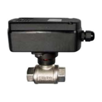
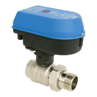
EMV 110..
ELECTRIC MOTOR ACTUATED BALL VALVE
KUGELHAHN MIT ELEKTROMOTORISCHEM ANTRIEB
GB
D
INSTALATION INSTRUCTION AND USER’S MANUAL
MONTAGEANWEISUNG UND BEDIENUNGSANLEITUNG
Installation should be carried out only by a qualified person !
Die Montage darf nur Fachmann ausführen !
DIMENSIONS AND ELECTICAL CONNECTION
ABMESSUNGEN UND ELEKTRISCHER ANSCHLUSS
BUILD-IN ROOM
EINBAURAUM
TECHNICAL DATA
TECHNISHE DATEN
Main connection ................... ........
Power consumption ............. .............................................
Rotation time......................... .................................................
Microswitch rating ............... ..........
Insullaton class .................... ......................
Actuator protection class .... ..............................................
Terminals............................... ..............................
Cable length.......................... ..................................................
Ambient temperature ........... ..............................
Humidity ................................ ....................
Fluid temperature.................
Nennspanung
Nennleistung
Rotationszeit
Belastung der Mikroschalter
Elektromotor isolationsklasse
Antreibsschutzart
Anschlussklemmen
Kabellänge
Umgebungstemperatur
Feucht
Temperatur des Fluids.......................
230VAC, 50Hz (EMV110..530)
*
3,5 W max
30s /90°
1(1)A, 250 VAC
F140°C
IP 55
0,5 ... 1 mm
1500 mm
0...50 °C
RH0% - 80% NON CONDESED
5...110°C max
24VAC, 50Hz (EMV110..533)
2
BUILD-IN POSITION
EINBAULAGE
PRIORITY / FORRANGLAGE
ALLOWED / MÖGLICHE LAGE
NOT ALLOWED !
UNERLAUBTE LAGE !
Fluids and gasses ( water,nonaggresive media ) up to 16 bar.
Flüssige und gasförmige Fluide ( Wasser, nicht aggressive Fluide ) bis zu 16 bar.
O-rings / O-Dichtungen
Valve
2 - EPDM
1 - EPDM
Ventil
Stem
M6x10
Gland
Einsatz
Unterlegsheibe
Träger
Bracket
Washer
Flange
Indicator
Flange cover
Spring
Nut (S19)
Anzeige
Flansch
Mutter
Flanschendeckel
Feder
Antriebswelle
INDEXING BRACKET
EINSTELLBARER TRÄGER
CONDITIONS FOR USE
BETRIEBSBEDINGUNGEN
Brown
Blue
Grey OPEN
Black
Gr/ge
PUMP
NEUTRAL
L
N
v/g
CLOSE
Schw ZU
Grau AUF
Blau NEUTRAL
Braun PUMPE
kg
kg
kg
Flow/pressure drop characteristic
Volumen Durchfluss und Druckabfall
2 - PTFE
1 - VITON
HYDRAULIC INSTALLATION: recomended instalation of the electric actuated ball valve
SCHEMA DER MASCHINENINSTALLATION: Empfohlener einbau des kugelventils mit elektromotorantrieb
1 manual stop valvel /
manuelles Absperrventil Kugelventil
2 strainer with the mesh width 0,65 mm /
Reinigungsfilter Y (für detaillierte
Informationen bitte rufen Sie uns an
lieferbar in Abmessungen von 1/2" bis 2”
3 motor actuated ball valve series
EMV 110...
Elektromotorantrieb mit Kugelventil
EMV 110…
IMPORTANT !
WICHTIG!
To extend the long term performance of the motorised ball valve it is recomended that
a strainer is situated prior to the valve. By installation must be observed to according to
relavant local standards.
Um die Lebensdauer des Ventil zu verlängern und Vernichtung der Dichtungen durch
mechanische Teile in der Installation zu verhindern wird der Einbau eines
Reinigungsfilters empfohlen. Die einschlägigen VDE+TÜV -
Verschriftensindzubeschten.
1 2
13
M
flow direction
Durchflußrichtung
Cx4-4010-EMV78NA-170236
1/2", 3/4", 1"