page 19
THERMOSTAT CONNECTION / ANSCHLUSS AUF DEM THERMOSTAT
PARRALLEL CONECTION / PARALLEL VERBINDUNG
MANUAL O
PERATION / HANDSTEUERUNG
ELECTRICAL SCHEME - ELEKTRISCHE STEUERSCHEMA
POSITION VALVE INDICATOR / ZEIGER DER VENTILLAGE
RELAY MODULE BUILD -IN INSTR UCTION / RELAIS - EINBAUEN
FIRŠT-ROTOTEHNIKA, s.p., Radegunda 54, SI-3330 Mozirje, SLOVENIJA
tel: +386 3 898 35 00, fax:+386 3 898 35 35, e-mail:info@first.si, http://www.first.si
SCHEMA DER MASCHINENINSTALLATION EMPFOHLENER EINBAU DES KUGELVENTILS MIT ELEKTROMOTORANTRIEB
12 13
M
Durchflußrichtung
IMPORTANT !
To extend the long term performance of the motorised ball valve it is recomended that a strainer
is situated prior to the valve. By installation must be observed to according to relavant local
standards.
WICHTIG!
Um die Lebensdauer des Ventil zu verlängern und Vernichtung der Dichtungen durch
mechanische Teile in der Installation zu verhindern wird der Einbau eines Reinigungsfilters
empfohlen. Die einschlägigen VDE+TÜV - Verschriftensindzubeschten.
1 manual stop valvel /
manuelles Absperrventil Kugelventil
2 strainer with the mesh width 0,65 mm /
Reinigungsfilter Y (für detaillierte
Informationen bitte rufen Sie uns an
lieferbar in Abmessungen von 11/4" bis 2"
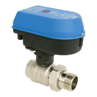
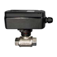
3 motor actuated ball valve series
EMV 110...
Elektromotorantrieb mit Kugelventil
EMV 110…
L
N
1
7
12
EMV 110..
L
N
1
7
12
EMV 110..
+
RM24
1 2 3 4
3-wire co nnection/3-Aderverbindung
switch over contact
normal open (close) contact
2-wire connection/2-Aderverbi ndung
Arbeits (Ruhig) kontakt
anschaltung kontakt
L
N
1
7
12
EMV 110..
+
RM24
EMV 110..
+
RM24
1 2 3 4
1
7
12
1 2 3 4
L
N
1 1
7 7
12 12
EMV 110.. EMV 110..
NO !
NEIN !
O.K.
with a relay / mit Relais
without relay / ohne Relais
1. Unscrew cower screws
2. Disconnect connection cord
3. Insert a relay module
4. Connect a relay module
according to scheme
5. Return the cover
Die Schrauben des Antriebdeckel
herausdrehen
Anschlusskabel ab
klemmen
Ralais Modul einsetzen
Relais Modul anschliessen
Antriebdeckel anschrauben
RELAY MODULE RM 24
RELAIS MODUL RM 24
Den Antrieb nach Ventil drücken
Den Antrieb drehen
Die Druckfeder bringt den Antrieb
wieder zurück und s
chnappt in die
eingestellte Lage
1. depress the actuator towards the valve
2. rotate the actuator
3. the
spring returns and snaps the actuator
FOR AUTOMATIC MOTOR OPERATION, RETURN
THE ACTUATOR INTO IT’S ORIGINAL POS ITION !
NACH HANDSTEUERUNG BRI
NGEN SIE DEN
ANTRIEB IN DIE ANFANGSLAGE ZURÜCK !
1.
2.
3.
INDIKATOR / ANZEIGE
red - port direction
rot - durchfluss
richtung
L1
N
1 3
4
6
7
9
10
12
factory connection
If necesery you can connect one
pump for each line. When the
way 1 is open, pump 1 is
operating, when the way 2 is
open, pump 2 is operating.
Man kann am beiden Gängen
eine Pumpe anschlüssen. Wenn
der Weg 1 geöfnet ist, Pumpe 1
läuft und wenn der Weg 2
geöfnet ist, Pumpe 2 läuft.
with a relay / mit Relais
ye/gr
brown
grey
black
blue
RM 24
black
blue
brown
ye/gr
red
yegr/grge
yegr/grge
black/schw
black/schw
W1
W1
W1
W2
W2
W2
grey/grau
grey/grau
blue/blau
blue/blau
brown/braun
brown/braun
M
M
M
 Loading...