The Fisher Isotemp® Premium Ovens 700 Series are laboratory instruments designed for precise temperature control in various applications. Available in three sizes—small (Models 725F and 725G), medium (Models 737F and 737G), and large (Models 750F and 750G)—these ovens offer PID Microprocessor control for operating temperatures ranging from 50°C (122°F) to 275°C (527°F).
Function Description:
The ovens are designed to maintain a set temperature for various laboratory processes. They come in two primary types: forced air and gravity flow models.
Forced air models (725F, 737F, 750F) provide improved temperature uniformity, control, and faster drying. In these models, fresh air enters through a bottom intake, is heated in a plenum below the chamber, and then circulated by a blower into wall plenums and the oven chamber in uniform flow patterns. Exhaust air is vented through a top port.
Gravity flow models (725G, 737G, 750G) draw air through a port under the oven floor. Heat-generated convection gently moves the air in a vertical circulation pattern, with exhaust air vented through a top port.
Temperature readouts and control parameters are displayed on red LEDs. Additional LEDs indicate when heater power is applied, an error condition is encountered, or the temperature is being set.
Safety features are integrated, including a safety backup in the controller software. If the primary heater control fails, the backup maintains control at 5°C above the set point, and an alarm LED illuminates. A circuit breaker protects the oven from power surges.
Important Technical Specifications:
- Operating Range: 50 to 275°C.
- Average Uniformity (@ 200°C, as per ASTM E145):
- Forced Air Models: +/-3°C
- Gravity Models: +/-4°C
- Control Resolution: 1°C
- Control Sensitivity: +/-0.5°C
- Recovery Time (@ 200°C, door open one minute):
- Model 725F: 1.0 minutes
- Model 725G: 2.0 minutes
- Model 737F: 2.0 minutes
- Model 737G: 3.0 minutes
- Model 750F: 2.5 minutes
- Model 750G: 4.0 minutes
- Rise Time to 275°C:
- Model 725F: 70 minutes
- Model 725G: 40 minutes
- Model 737F: 80 minutes
- Model 737G: 80 minutes
- Model 750F: 80 minutes
- Model 750G: 100 minutes
- Air Exchanges per Hour (as per ASTM E145):
- Model 725F: 43
- Model 725G: 24
- Model 737F: 29
- Model 737G: 16
- Model 750F: 22
- Model 750G: 12
- BTU/hr Output:
- @100°C: 725F (1125), 725G (470), 737F (1325), 737G (1040), 750F (1325), 750G (1150)
- @200°C: 725F (2750), 725G (1325), 737F (2925), 737G (2025), 750F (3095), 750G (2040)
- Electrical Requirements (120 V, 50/60 Hz or 240 V, 50/60 Hz):
- Models 725F & 725G: 1300 W
- Models 737F & 737G: 1800 W
- Models 750F & 750G: 1800 W
- Chamber Volumes:
- Models 725F & 725G: 2.5 cu ft
- Models 737F & 737G: 3.8 cu ft
- Models 750F & 750G: 5.0 cu ft
- Chamber Dimensions (W x D x H):
- Models 725F & 725G: 18 x 18 x 13.5 in
- Models 737F & 737G: 18 x 18 x 20 in
- Models 750F & 750G: 18 x 18 x 26.5 in
- Shelving:
- Models 725F/G: Max 5 shelves (one provided)
- Models 737F/G: Max 8 shelves (one provided)
- Models 750F/G: Max 11 shelves (two provided)
Usage Features:
- Installation: Requires a 2 ft x 2 ft area on a bench capable of supporting 120-135 lbs, depending on the model. A 2-inch air clearance on all sides and top is necessary for heat dissipation. No extension cords should be used.
- Unpacking: After unpacking, users should locate all items listed in the manual, including the oven assembly, shelves, shelf supports, and instruction manual. Any missing items or shipping damage should be reported to Fisher.
- Preparing the Oven: Involves installing the shelf, ensuring all packing material is removed from the chamber, and connecting the line cord to an appropriate electrical outlet. No preliminary adjustments or calibrations are required for initial operation, though an initial calibration may be performed using the display offset feature.
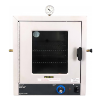
- Power Switch: A front-panel-mounted rocker-type switch combines power control and a circuit breaker. Pressing the "I" (upper) half turns the oven on, and "0" (lower) half turns it off. To reset the breaker, turn the switch off, then back on.
- Controls:
- Display: A bright, one-half inch LED numeric display shows the oven temperature. Smaller LEDs indicate program status, alarm conditions, and heater activity.
- Keypad: A four-key tactile keypad with "Menu," "Set," "Increase," and "Decrease" buttons.
- "Set" displays the set temperature and, when used with "Increase" or "Decrease," changes it.
- "Increase" and "Decrease" adjust the set temperature. Holding them down provides rapid adjustment, while pressing and releasing increments/decrements by one degree.
- "Menu" with "Set" accesses the temperature display offset entry.
- Operation: To set a temperature, turn on the power, press and hold "Set," then use "Increase" or "Decrease" to adjust the temperature. Release the keys once the desired temperature is shown.
- Safety Precautions: The unit is not explosion-proof and should not be used with flammable or combustible materials. Fumes and spillage from acidic solutions can corrode the stainless steel chamber, so a neutral pH must be maintained. The heater is at the bottom of the unit, and its surface temperature can exceed the set point, so items should not be placed directly on the heater cover. Users should wear insulated gloves and safety goggles, use tongs, and never stand in front of an open oven.
- Limit Alarms: The 700 Series controllers feature a deviation alarm that activates if the actual oven temperature differs from the set temperature by more than 5°C. This limit is fixed. When triggered, the alarm indicator LED lights, the display shows "EEE," and heater power is interrupted. Changing the set temperature will shift the alarm temperature accordingly. If the set temperature is changed to a value more than 5°C below the present oven temperature, the alarm will trip until the oven cools down to 5°C above the new set point.
- Display Offsets: Allows operators to adjust the displayed temperature to match a calibrated thermometer at a specific point within the oven. The displayed temperature is the actual oven temperature plus or minus the offset. To enter an offset, press "Menu" (display shows "CAL"), then press and hold "Set" to view the current offset. Use "Increase" or "Decrease" to change the offset, then release "Set" and press "Menu" to return to normal control.
Maintenance Features:
Service procedures requiring access to the electronics compartment should only be performed by qualified service personnel due to exposure to line voltage. The oven must be disconnected from the power source and allowed to cool to ambient temperature before any repairs.
- Replacing the Door Gasket:
- Turn off power and open the door.
- Lift the door off its hinges and lay it flat.
- Note the joint position of the old gasket.
- Bend back the old gasket and remove Phillips head screws.
- Remove the old gasket.
- Loosely install two screws to align the stainless steel liner and door wrap.
- Install the new gasket starting at the joint, stretching it around corners to avoid bunching.
- Install Phillips head screws at each corner to keep the gasket stretched.
- Install remaining screws, ensuring no gap at the joint.
- Reinstall the door onto the hinge pins.
- Replacing the Door Hinges:
- Remove the chamber door.
- Remove the two mounting screws for the defective hinge.
- Replace the hinge and secure with screws.
- Put the door back on hinges.
- Replacing the Door Handle:
- Remove two screws holding the latch cover.
- Remove two screws holding the defective handle.
- Mount the replacement handle with two screws.
- Adjusting the Door Cam:
- Open the door and remove screws holding the latch cover.
- Locate nuts securing the tongue on the cam shaft.
- Loosen the outside nut (do not remove).
- Adjust the inside nut (one full turn clockwise draws the door 1/16" closer).
- Tighten the outside nut to secure the cam tongue.
- Secure the latch cover.
- Accessing the Electronics Compartment:
- Disconnect the power cord.
- Remove the chamber door.
- Slide the oven forward until the front bezel is at least three inches from the bench edge.
- Prop up the oven front with shims (1.5-2 inches thick).
- Remove screws securing the bezel from the bottom of the oven.
- Slide the oven back to rest the bezel on the bench, then rotate the bottom of the bezel out from the oven. The top clips will loosen, but wiring remains connected.
- Carefully set the bezel on the bench.
- Replacing the Heater:
- Disconnect the power cord.
- Remove two screws securing the heater cover, then lift and slide the cover forward. Set aside.
- Remove two nuts and shake-proof washers from heater leads, then pull terminals off studs.
- Remove two screws securing the heater to the cabinet. Slide the heater forward, lift the back, then slide it back and out.
- Install the replacement heater and reassemble in reverse order.
- Replacing the Cooling Fan:
- Access the electronics compartment.
- Remove two fan power wires from push-on terminals.
- Remove three mounting screws holding the fan.
- Install the replacement fan, ensuring the airflow arrow points into the oven chassis, and reassemble.
- Replacing the Circulating Fan Motor:
- Access the electronics compartment and remove the heater cover.
- Loosen the set-screw holding the fan blade onto the motor shaft with an Allen wrench. Note the flat side of the shaft.
- Remove two electrical leads from the fan motor at the terminal strip on the front of the oven bezel.
- Lay the oven on its back.
- Detach the controller housing (oven bottom) by removing eight screws (two on each side, four on the bottom).
- Locate two access holes for motor mounting nuts in the oven floor.
- Push an 11/32-in nut driver through the front access hole, gently pushing aside insulation, to reach and remove the front motor mounting nut and washer. Repeat for the back nut.
- Remove the fan motor.
- Install the replacement fan motor and reassemble in reverse order.
- Replacing the Controller:
- Access the electronics compartment.
- Locate terminal blocks on the controller, noting wire colors and locations, then remove all wires.
- Remove four screws holding the controller to the bezel.
- Install the new controller and reattach wires.
- Check wiring connections against the schematic, ensuring the line power wire is attached to the correct terminal (120V or 240V).
- Check switch DS1 setting: ON for forced air, OFF for gravity. Switch B should always be OFF.
- Replacing the Solid State Relay (SSR):
- Access the electronics compartment.
- Consult the schematic and locate the SSR (mounted on bezel).
- Remove four lead wires from screw-down terminals.
- Remove two Phillips screws mounting the SSR to the bezel.
- Lift out the SSR. Install the new SSR, ensuring the thin, conductive pad remains between the SSR and the bezel.
- Reassemble in reverse order.
- Replacing the Safety Relay:
- Access the electronics compartment.
- Consult the schematic and locate the safety relay (mounted on bezel).
- Remove four lead wires from push-on terminals.
- Remove two Phillips screws mounting the safety relay to the bezel.
- Lift out the safety relay.
- Install the replacement safety relay and reassemble.
- Replacing the Control Thermocouple:
- Access the electronics compartment.
- Remove thermocouple wires from the controller's 6-terminal connector by loosening two screws.
- On the oven roof, locate and remove the clip holding the thermocouple.
- Pull the thermocouple forward into the oven chamber, exposing about 6 inches of wire.
- Cut the thermocouple wire to remove the sheath.
- Securely loop the cut end of the defective thermocouple with the two leads of the replacement thermocouple. Wrap tape over the loops.
- Gently pull the defective thermocouple out through the electronics compartment while guiding the replacement thermocouple into place.
- Consult the schematic and reverse steps 1-3 to complete installation, ensuring the yellow conductor is under the (+) tab and the red under the (-) tab.