EasyManua.ls Logo

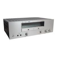
Fisher BA-6000 - Schematic Diagram

Fisher BA-6000
13 pages
To Next Page IconTo Next Page
To Previous Page IconTo Previous Page
Loading...
SCHEMATIC
DIAGRAM
ewe
.
o
le
ee
pas
08,
INPUT/
METER
P.C.B.
ass'Y
Qo1
,
02
por
,02
08442*2
Q03,04
2SA984
12
1310
-
4001-03650
25093642
a
eee
PEAK
INO.
P.C.B.
ASS'Y
1310-4001-03660
1390-400!-03670
ES»
ST
*
aS
§
©
_
ee
POWER
AMP.
P.C.B.
ASS'Y
1510-
4001-05620
027
2e
Ras
013
~16
D
3K
o23,
24
2502259
72
280438
"2
1s188
54
SE
o
POWER METER
ec)
14
Srv}
,
co
+
-
ata
o
fs
ore
:
j
OD
,
.
jen}
rl
i
ao
6)
)
)
O
Qu~
18
K
NUM4558
DO
A
mee
aan
rs
ral
_|
>
ib
aie
Co
by
47/25
2
W048
1750
Ri2
007
,
08
R22
cd
ark
ox
15188
«2
SPEAKER
SYSTEM
A
em
*
a
#
|
sp.
SELECT
PC.B
ASS'Y
1310-4001-
03640
al
al
a
2
0S442"8
019
wz130
1
u
'
aa}
a
(>
(4
SPEAKER
coTs
p03
SYSTEM
8
1763
+!
ce
cz
por~
04
01,02
pz2sore
ei
2SK1312
2
Qte~
22
250758
%
4
ooo
a
eg
toe
$60/2W
110_120/1W.
ca)
.
EAN
oot
=
$10VB20
p29~32
BZ250"4
9
2051
|
100
;
CO3~
06
0.017900
4
4
icot
,
02
STKOOIO
«
2
VOLTAGE
SELECTOR
034
035
0s442
MZ330
esa)
Ot
SiRBAZO
————_——
eo
i:
<.
POWER
SUPPLY
_P.C.B.
ass'Y
110/220V
1310-4001-
03650
NOTES:
1
All
resistors
values
are
indicated
1
Hohe
K-10"
-M=10°)
b.
All
voltages
*
10%
with
respect
chassis
ground
c
Na
signals
at
input
terminals
2.
All
capacitors
values
are
indicated
a
“wh”
we104}
San
atarane
psheatent
ob
the
schasmanees
are
measured
under
the
d.
AC
input
at
220
volts
50
Hz
4
This
is
a
fundamental
schematics
diagram.
Some
products
may
4
tact
natice
—-14—-

Related product manuals