Lit. No. 49599, Rev. 05 5 April 1, 2018
29250, 29350, 97000, 97000-1, 97100, 97100-1
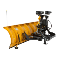
HEADGEAR TO A-FRAME ASSEMBLY
NOTE: For easier assembly and installation,
vehicle and all snowplow components should
be on a smooth, level, hard surface, such as
concrete.
1. Set aside the blade guides, angle frame, and parts
bag. The vehicle electrical harnesses and the
Owner's Manual packet are in the bag with the
headlamp box.
2. Remove the packaging hardware securing the
headgear to the A-frame, except the clevis pins
and shipping brackets.
3. Remove the blocking and hardware securing the
A-frame to the pallet.
4. While supporting the headgear, remove and
retain the four clevis pins and discard the shipping
brackets.
5. Align the holes in the headgear assembly with the
middle hole in the A-frame. Attach the A-frame to
the headgear assembly with two 1-1/4" clevis pins
and 1/4" x 2" cotter pins. Insert the pins from the
outside of the headgear. Verifi cation of proper
A-frame position will be made during Final
Adjustments.
Headgear
ssembly
A-Frame
1/4" x 2"
Cotter Pin
1-1/4"
Clevis Pin
A-FRAME TO BLADE ASSEMBLY
1. Place the slots in the angle frame mounting hooks
over the pins that attach the rib to the base angle.
2. Rotate the angle frame up until the anchor plate
holes line up with the holes in the ribs.
3. Attach each anchor plate to the ribs using two
3/4" x 2" cap screws and 3/4" locknuts. Tighten
fasteners according to the torque chart.
Mounting
Hook
3/4"
Locknut
3/4" x 2"
Cap Screw
Anchor
Plate
Tighten according
to torque chart.
 Loading...