Fiskars Help Line: 1-877-201-3260 videos & more at: skars.com/reelmowers Fiskars Help Line: 1-877-201-3260 videos & more at: skars.com/reelmowers
Assembly
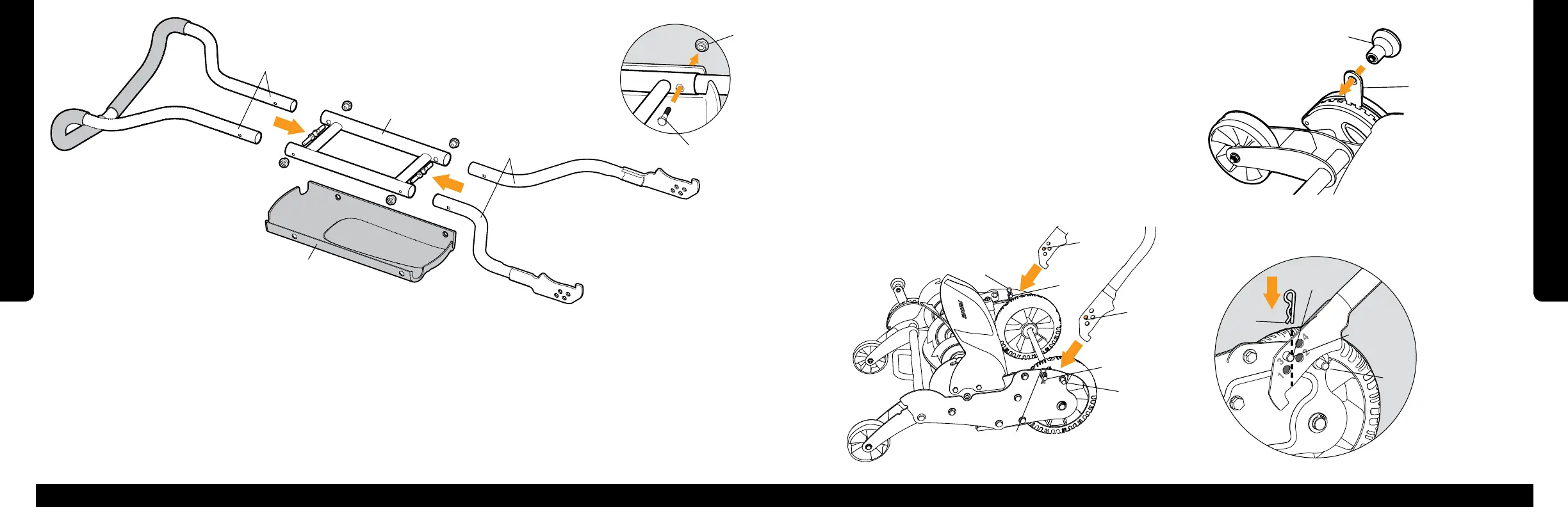
Cut Height Adjustment Assembly
1. Check the front of the cutting reel for a clear, thin plastic shipping shield that extends
downward from the grass discharge chute. If the shield is present, remove and discard
it prior to first use.
2. Screw the cut height adjustment knob (G) tightly onto the exposed lever (H) by hand.
Attaching the Handle
1. Remove the two cotter pins (I) from the handle-mount pegs (J).
2. Slide hole number 3 (K) of the handle onto the handle-mount pegs (J)
and then release the handle until it rests on the handle-stop peg (L).
3. Insert the cotter pins (I) to secure the handle into place.
Assembly
G
H
K
L
Attaches
to inside of
frame
Attaches
to outside of
frame
I
J
J
I
L
K
K
J
I
6 7
A
B
C
D
E
F
G
6. Align holes in handle sections and shroud (D). Slide a handle bolt (E)
through from the inside, so that the end comes through the hole of the handle
shroud. Repeat for the remaining three handle bolts.
7. Align the hex-shaped bolt head with the hex-shaped cutout in the center
handle section (A) and then hand tighten a handle nut (F) onto the bolt.
Repeat for the remaining three handle nuts.
8. Using a wrench, tighten the four handle nuts (F) until they are snug.
Handle Assembly
1. The only tool required for assembly is a 11 mm wrench or socket.
2. Lay out the handle parts as shown above. Note the center handle section
(A) is symmetrical.
3. Insert the free ends of the upper handle section (B) into the center handle
section (A), making sure the arch of the upper handle section is down.
Roughly align the holes.
4. Insert the two lower handle sections (C) into the center handle section (A),
making sure the pointed ends of the lower handle sections are up as shown.
Roughly align the holes.
5. Slide handle shroud (D) into place from below with the Fiskars logo facing
down and toward the upper handle section (B).
The following parts are
included in the hardware bag:
Handle nuts (4)
Handle bolts (4)
Cut height adjustment knob (1)