EasyManua.ls Logo

FitSpine Inversion table User Manual

FitSpine Inversion table
6 pages
To Next Page IconTo Next Page
Page #1 background imageLoading...
Page #1 background image
Assembly Instructions
WARNING
!
Want more information about your FitSpine refer to the:
1. Owner’s Manual
2. Contact Customer Service at 1-800-847-0143
3. Visit www.FitSpine-System.com
If you have any problems assembling the equipment,
or questions about its use, please contact customer service at:
STL International, Inc.
9902 162
nd
St. Ct. E., Puyallup, WA 98375
Toll Free (Phone) 800-847-0143 (Fax) 800-847-0188
Local (Phone) 253-840-5252 (Fax) 253-840-5757
(e-mail) info@FitSpine-System.com (web) www.FitSpine-System.com
U.S. patents apply.
FitSpine™ is a registered trademark of STL International, Inc.
Specications subject to change without notice.
© COPYRIGHT 2009, STL International, Inc.
International Law Prohibits Any Copying, 0610-3
LS-2001
Read the Owner’s Manual thoroughly before using your FitSpine Trainer inversion table.
Improper settings could result in serious injury or death!
Question and Answer IconNeed help?

Do you have a question about the FitSpine Inversion table and is the answer not in the manual?

FitSpine Inversion table Specifications

General IconGeneral
Weight Capacity300 lbs
Frame MaterialSteel
FoldableYes
AdjustabilityYes
Ankle Locking SystemYes
ModelFitSpine Series (Various Models)
Height Range4'10" - 6'6"

Summary

Important Safety Instructions

General Safety Warnings

Key safety precautions and warnings for using the inversion table, including user limits and supervision.

Adjustments, Maintenance, and Storage

Adjusting Roller Hinge Setting

Instructions on how to adjust the roller hinge settings for the inversion table.

Table Maintenance

Guidance on cleaning and maintaining the inversion table mat and components.

Storing the Inversion Table

Steps for folding and storing the inversion table compactly for convenience.

Assembly Parts and Steps

Parts List for Assembly

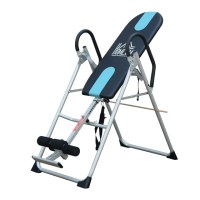
List of all parts and their corresponding item numbers required for assembling the FitSpine Trainer.

Assembly Step Ten

Attaching the nylon tether and owner's manual for rotation limit and reference.

Assembly Step Eleven

Final checks before use: testing rotation, fastener security, and warranty registration.

Assembly Step Six

Attaching the rear bar with ankle clamps to the main shaft.

Assembly Step Seven

Installing the foot platform assembly onto the bar.

Assembly Step One

Attaching stability feet to the A-frame base.

Assembly Step Two

Locking the roller hinges onto the table bed assembly.

Assembly Step Three

Attaching the table bed assembly to the A-frame.

Assembly Step Four

Inserting the main shaft into the table bed assembly.

Assembly Step Five

Installing the front foam rollers onto the front ankle bar.