EasyManua.ls Logo

FIXUM DUDE BD-1 - User Manual

FIXUM DUDE BD-1
20 pages
Print Icon
To Next Page IconTo Next Page
Loading...
BD-1 DROID KIT CARD
ASSEMBLY INSTRUCTIONS
Question and Answer IconNeed help?

Do you have a question about the FIXUM DUDE BD-1 and is the answer not in the manual?

Summary

BD-1 Droid Kit Card Assembly Instructions

BD-1 Droid Parts Identification

Overview of all parts included in the BD-1 Droid Kit, with labels for easy identification.

Initial Body Assembly (Steps 1-4)

Instructions for assembling the primary body sections of the BD-1 Droid using parts B, C, D, and F.

Attaching Side Components and Antennae (Steps 5-9)

Detailed steps for attaching side components E and G, and installing antennae H and I.

Head and Torso Assembly (Steps 10-14)

Assembly of the droid's head and torso, connecting various detail parts J through P.

Leg and Foot Assembly (Steps 15-21)

Final assembly of the droid's legs and feet, connecting parts Q, R, S, T, and U to complete the model.

Other Available Kit Cards

Information about additional kit cards offered by FIXUMDUDE.COM, including Millennium Falcon and Tie Interceptor.

Overview

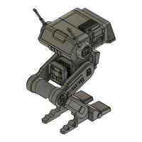
This document provides assembly instructions for a BD-1 Droid Kit Card, a model kit produced by FIXUMDUDE. The kit allows users to build a miniature replica of the BD-1 droid from the Star Wars universe.

Function Description:

The BD-1 Droid Kit Card is a static model kit designed for hobbyists and fans of Star Wars. Its primary function is to provide an engaging and educational assembly experience, resulting in a displayable miniature of the BD-1 droid. The kit is intended for personal enjoyment, collection, and display, rather than functional use. It serves as a collectible item and a creative project for individuals interested in model building and Star Wars memorabilia.

Important Technical Specifications:

The kit consists of multiple gray plastic parts, molded onto a sprue, which need to be detached and assembled. The parts are labeled with letters (A through U) for easy identification and reference during the assembly process. The final assembled model represents the BD-1 droid, characterized by its distinctive head, body, and two-legged design.

Key components include:

  • Head Assembly: Composed of parts A, B, C, D, E, F, G, H, I, and J. This section forms the upper part of the droid, including its "eyes," head fins, and antennas.
  • Body Assembly: Composed of parts K, L, M, N, O, and P. This section forms the central torso of the droid, connecting the head to the legs.
  • Leg Assemblies: Composed of parts Q, R, S, T, and U. These sections form the two articulated legs and feet of the droid, allowing it to stand.

The assembly process involves connecting these parts using a system of clips, slots, and connectors, as indicated by red arrows in the instructions. Specific attention is given to the orientation of parts, such as "clip toward the back," "fins up and toward front," "longer connector to the right," "antenna should face up and toward the back with the slot aligned to clips," "neck connector angles toward the front," "single connector facing up and toward back," "grooves facing down and toward back," "grooves on bottom and back of body match up," and "top of leg should angle back and the bottom should angle forward as shown here," and "connector for front of foot should face forward."

Usage Features:

The BD-1 Droid Kit Card is designed for straightforward assembly, making it accessible to a range of model builders. The instructions are presented in a step-by-step visual format, with each step clearly numbered and accompanied by detailed diagrams. Red arrows indicate the direction and points of connection for each part.

The assembly process can be broken down into several main stages:

  1. Head Base Assembly (Steps 1-4):
    • Step 1: Connect part B to part D, ensuring the arrow on D points forward and the clip on B faces the back.
    • Step 2: Connect part C to the assembled B and D, ensuring the fins on C face up and toward the front.
    • Step 3: Connect part A to the assembled B, C, and D.
    • Step 4: Connect part F to the assembled B, C, and D, ensuring the fins on C remain up and toward the front.
  2. Head Side Panels and Antennas (Steps 5-8):
    • Step 5: Attach part E to the side of the head assembly (parts A and C), ensuring the longer connector on E is to the right.
    • Step 6: Attach part G to the other side of the head assembly (parts A and C), and connect part E to the head.
    • Step 7: Attach part H (antenna) to the head assembly (parts A and C), ensuring the antenna faces up and toward the back, with the slot aligned to clips.
    • Step 8: Attach part I (antenna) to the head assembly (parts B and C), ensuring the antenna faces up and toward the back, with the slot aligned to clips.
  3. Neck Connector (Step 9):
    • Step 9: Insert part J (neck connector) into the bottom of the head assembly (part D), ensuring the neck connector angles toward the front.
  4. Body Assembly (Steps 10-14):
    • Step 10: Connect part M to part K, ensuring the single connector on M faces up and toward the back, and the grooves on K face down and toward the back. Note the grooves at the back of K.
    • Step 11: Connect part L to the assembled K and M, ensuring the single connector on L faces up and toward the back. Note the grooves at the back of K.
    • Step 12: Connect part N to the assembled K, L, and M.
    • Step 13: Connect part P to the assembled K, L, and M, ensuring the grooves on the bottom and back of the body match up.
    • Step 14: Attach part O to the top of the body assembly (parts K, L, N, P).
  5. Connecting Head to Body (Step 15):
    • Step 15: Connect the assembled head (parts A, B, C, D, E, F, G, H, I, J) to the assembled body (parts K, L, M, N, O).
  6. Leg Assembly 1 (Steps 16-18):
    • Step 16: Attach part Q to the body assembly (parts K, L, M, N, O).
    • Step 17: Attach part R to part Q. Ensure the top of the leg (Q) angles back and the bottom (R) angles forward as shown in the diagram. The connector for the front of the foot should face forward.
    • Step 18: Attach part U to part R.
  7. Leg Assembly 2 (Steps 19-21):
    • Step 19: Attach part S to the body assembly.
    • Step 20: Attach part T to part S. Ensure the top of the leg (S) angles back and the bottom (T) angles forward as shown in the diagram. The connector for the front of the foot should face forward.
    • Step 21: Attach part U to part T.

The final product is a complete BD-1 droid model, ready for display. The kit promotes fine motor skills, spatial reasoning, and adherence to instructions.

Maintenance Features:

As a static model kit, the BD-1 Droid requires minimal maintenance once assembled.

  • Cleaning: The model can be gently dusted with a soft brush or cloth to remove accumulated dust. Avoid using harsh chemicals or abrasive materials, which could damage the plastic.
  • Storage: Store the model in a stable location, away from direct sunlight, extreme temperatures, and high humidity to prevent material degradation or discoloration.
  • Repair: In case of accidental breakage, plastic model glue can be used to reattach broken parts. Care should be taken to apply glue sparingly to avoid visible residue.

The kit is designed for durability once assembled, but it is not intended for rough handling or play. Its primary purpose is display.

FIXUMDUDE also offers other Star Wars-themed kit cards, including the Millennium Falcon, Imperial Shuttle, Tie Interceptor, and Landspeeder, available at FIXUMDUDE.COM, indicating a broader product line for collectors.

FIXUM DUDE BD-1 Specifications

General IconGeneral
BrandFIXUM DUDE
ModelBD-1
CategoryRobotics
LanguageEnglish