- 17 -
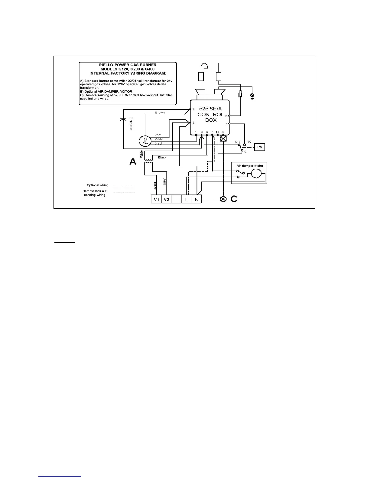
FACTORY WIRING DIAGRAM
B
NOTE:
1. This burner is approved for use without the motorized air damper. In these
instances optional wiring is used
2. The SAFETY SWITCH on the 525 SE CONTROL BOX is equipped with a
contact allowing remote sensing of burner lockout. The electrical connection
is located on the CONTROL BOX terminal 4 as indicated. Should burner
lockout occur, the 525 SE CONTROL BOX will supply a power source of 120
Vac to the connection terminal. The maximum allowable current draw on this
terminal is 1 A.