MGS200 Installation Guide Feb, 10
Condential Version 1.4
Conrming proper operation:
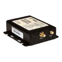
Connect the antenna cables to the appropriate locations
on the MGS.
Check the power light on the MGS
Check for cellular connectivity light (Flushing Blue).
•
•
•
Red LED Description
Green LED Description
OFF
1 – 1
2 – 1
2 – 2
2 – 3
2 – 4
3 – 1
3 – 2
3 – 3
3 – 4
3 – 5
OFF
Flash
Slow
Fast
No faults detected
License Key Exp.
CDMA Module fault
Not Activated
No CDMA Signal
Network not found
GPS Module fault
GPS Annt. Open/Short
GPS Not track (0 Sat.)
GPS No x (<3 Sat.)
GPS No time
Power Down mode
Low power mode
Full power ignition O
Full power ignition On
Page 05
Applies to Serial #
000003259999 ( - )
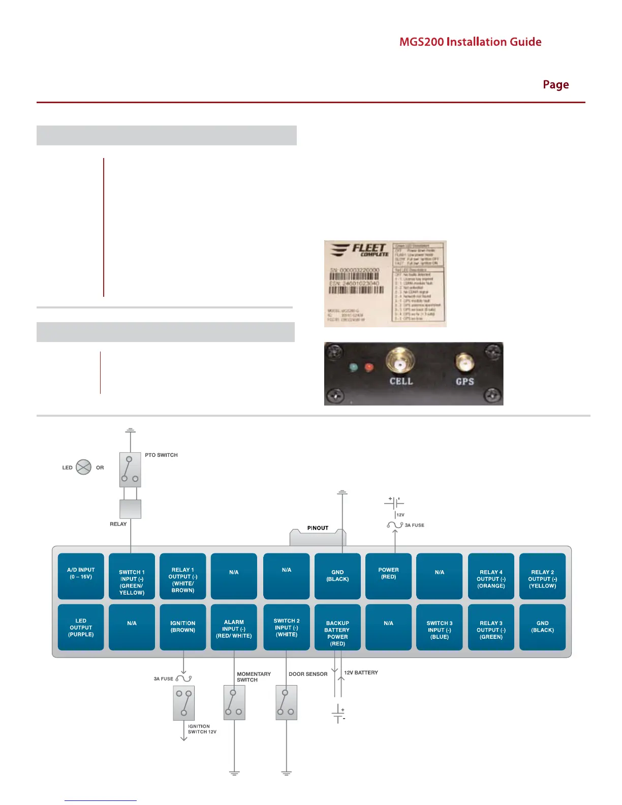
MGS 200-G INPUT INSTALLATION DIAGRAM