K420 DE/EN/FR2
N-EUPEX, N-EUPEX-DS
Elastische Kupplungen Flexible Couplings Accouplements élastiques
Grundprinzip Basic Pattern Principes
Inhaltsübersicht Contents Sommaire
2.1 2.2
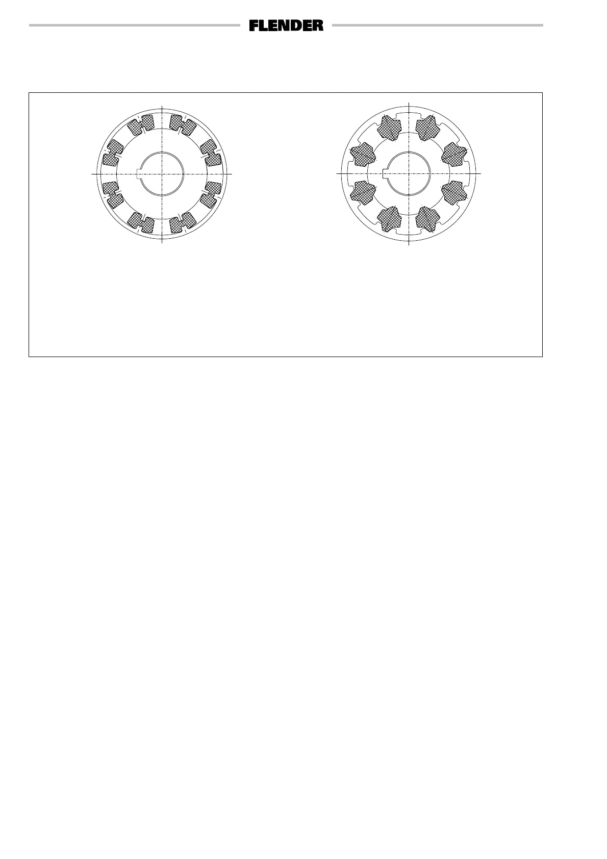
Die durchschlagsichere N-EUPEX-Kupplung
(Bild 2.1)
Die Nockenkupplung, die beim Ausfall der elasti-
schen Elemente das Drehmoment über die Guß-
teile notüberträgt (mit Durchschlagsicherung).
Die durchschlagende N-EUPEX-DS-Kupp-
lung (Bild 2.2)
Die Nockenkupplung, die beim Ausfall der elasti-
schen Elemente die Trennung von An- und Ab-
trieb ermöglicht (ohne Durchschlagsicherung).
The fail-safe N-EUPEX coupling (Fig. 2.1)
Pin coupling which upon failure of flexible
elements makes emergency torque transmis-
sion possible via the metallic parts (with fail-safe
device).
N-EUPEX-DS coupling, without fail-safe
device (Fig. 2.2)
Pin coupling which upon failure of flexible
elements allows disconnection of input and out-
put side (without fail-safe device).
L’accouplement N-EUPEX à sécurité positive
(Fig. 2.1)
L’accouplement à plot qui transmet le couple par
les doigts métalliques lorsque les éléments élas-
tiques sont détériorés.
L’accouplement N-EUPEX-DS sans sécurité
positive (Fig. 2.2)
L’accouplement à plot qui lors de la détérioration
des éléments élastiques sépare la machine
motrice de la machine réceptrice.
Inhaltsübersicht:
N-EUPEX-Kupplungen
Seite
Charakteristische Vorzüge 3
Aufbau und Wirkungsweise 4-5
Technische Hinweise für den Einbau 6
Größenbestimmung 7
Berechnungsbeispiele 10
Nenn-Leistungen 11
N-EUPEX-Kupplungen für IEC-Norm- 12
motoren
Fertiggebohrte N-EUPEX-Kupplungsteile 13
Bauartenübersicht für N-EUPEX-Kupplungen 14
Maße, Massenträgheitsmomente und
Gewichte für N-EUPEX-Kupplungen
Bauarten B und A 15
Bauarten E und D zum Anflanschen 16
Bauart M zum Anflanschen 17
Bauarten O und P mit Bremstrommel 18
Bauart H mit Zwischenhülse 19
Bestellbeispiele 20
Beispiele für Sonderausführungen 21
N-EUPEX-DS-Kupplungen
Charakteristische Vorzüge 3
Aufbau und Wirkungsweise 22-23
Technische Hinweise für den Einbau 24
Größenbestimmung 25
Berechnungsbeispiele 28
Nenn-Leistungen 29
N-EUPEX-DS-Kupplungen für IEC-Norm- 30
motoren
Bauartenübersicht für N-EUPEX-DS 31
Kupplungen
Maße, Massenträgheitsmomente und
Gewichte für N-EUPEX-DS-Kupplungen
Bauarten BDS und ADS 32
Bauart HDS mit Zwischenhülse 33
Bestellbeispiele 34
N-EUPEX, N-EUPEX-DS-Kupplungen
Paßfedern und Keile, Passungsauswahl 35
Contents:
N-EUPEX couplings
Page
Characteristic features 3
Design and operation 4-5
Design hints for fitting 6
Selection of size 8
Calculation examples 10
Nominal power ratings 11
N-EUPEX couplings for IEC motors 12
Finish-bored N-EUPEX coupling parts 13
Types of N-EUPEX couplings 14
Dimensions, mass moments of inertia
and weights of N-EUPEX couplings
Types B and A 15
Types E and D for flange connection 16
Type M for flange connection 17
Types O and P with brake drum 18
Type H with intermediate sleeve 19
Ordering examples 20
Special designs 21
N-EUPEX-DS couplings
Characteristic features 3
Design and operation 22-23
Design hints for fitting 24
Selection of size 26
Calculation examples 28
Nominal power ratings 29
N-EUPEX-DS couplings for IEC motors 30
Types of N-EUPEX-DS couplings 31
Dimensions, mass moments of inertia
and weights of N-EUPEX-DS couplings
Types BDS and ADS 32
Type HDS with intermediate sleeve 33
Ordering examples 34
N-EUPEX, N-EUPEX-DS couplings
Parallel and taper keys, ISO fits 35
Sommaire:
Accouplements N-EUPEX
Pages
Avantages caractéristiques 3
Construction et fonctionnement 4-5
Renseignements techniques sur le montage 6
Choix des tailles 9
Exemples de sélection 10
Puissances nominales 11
Accouplements N-EUPEX pour moteurs 12
selon norme I.E.C.
Alésages définitifs des parties 13
d’accouplement
Différents types d’accouplements N-EUPEX 14
Dimensions, moments d’inertie et poids
pour les accouplements N-EUPEX
Types B et A 15
Types E et D à flasque bride 16
Type M à flasque bride 17
Types O et P avec poulie frein 18
Type H avec entretoise 19
Exemples de commandes 20
Exemples d’exécutions spéciales 21
Accouplements N-EUPEX-DS
Avantages caractéristiques 3
Construction et fonctionnement 22-23
Renseignements techniques sur le montage 24
Choix des tailles 27
Exemples de sélection 28
Puissances nominales 29
Accouplements N-EUPEX-DS pour 30
moteurs selon norme I.E.C.
Différents types d’accouplements 31
N-EUPEX-DS
Dimensions, moments d’inertie et poids
pour les accouplements N-EUPEX-DS
Types BDS et ADS 32
Type HDS avec entretoise 33
Exemples de commandes 34
Accouplements N-EUPEX, N-EUPEX-DS
Tolérances ISO, clavetages 35
 Loading...