EasyManua.ls Logo

Flex-a-Lite 31149 User Manual

Flex-a-Lite 31149
2 pages
To Next Page IconTo Next Page
Page #1 background imageLoading...
Page #1 background image
Wiring Diagram
1a. Connect the motor wires to the control module
(Red wire to the "M+" terminal and black wire to
the "M-" terminal).
1b. Disconnect the negative battery lead for
safety while finishing the wiring. Use the large
diameter red (10 AWG) wire to run power directly
from the battery positive (+) terminal to the "B"
terminal on the control module. Connect the fuse
holder in-line with this wire, as shown, but do not
insert the fuse yet. Use the yellow
female, ring, and butt connectors provided.
Part number 31149
Temp. Control Module
1c. Use the large diameter black (10 AWG) wire to
run from the negative (-) battery terminal to the "G"
terminal on the control module. Use the yellow
female connector and ring connector provided.
1d. Use the small diameter red wire (14 AWG) to connect the "+" terminal on the
control module to a positive power source.
NOTE: Attaching this wire to an
ignition-controlled source will shut off the fan when the engine is turned
off. Attach this wire to an uninterrupted (always hot) power source to allow
the fan to continue running after the engine is shut off.
Use the blue female
connector and fuse taps (included) if necessary.
10-07-05 part no. 99842 Page 1 of 2
Question and Answer IconNeed help?

Do you have a question about the Flex-a-Lite 31149 and is the answer not in the manual?

Flex-a-Lite 31149 Specifications

General IconGeneral
BrandFlex-a-Lite
Model31149
CategoryTemperature Controller
LanguageEnglish

Summary

Wiring Diagram and Connections

Connect Motor Wires

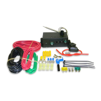
Connect motor wires to the control module's M+ and M- terminals.

Connect Battery Power

Connect large diameter red wire from battery positive to 'B' terminal, with fuse holder.

Connect Ground Wire

Connect large diameter black wire from battery negative to 'G' terminal.

Connect Positive Power Source

Connect small red wire to a positive power source; ignition-switched or always hot.

Installation Steps

Optional Control Features

Configure for optional AC control or manual switch operation.

Secure Wiring and Finalize

Secure wires with zip ties, reconnect battery, and insert fuse.

Install Temperature Probe

Insert probe into radiator fins near the inlet hose and reinstall insulator cap.

Adjust Temperature Control Knob

Calibrate knob by turning counter-clockwise until fan activates at desired temperature.