EasyManua.ls Logo

Flex-a-Lite 31173 - User Manual

Flex-a-Lite 31173
2 pages
Print Icon
To Next Page IconTo Next Page
Loading...
Installation and Wiring
Quick Start Motor Control Kit
#31173, #31174
Follow these instructions carefully to avoid damaging the control unit., fan
motors, and your vehicle! When crimping wires, always use a quality crimping
tool (DO USE PLIERS OR OTHER DEVICES).
**Before installation of your Flex-a-lite fan, be sure that your batteries and charging
system are operating correctly. Poor batteries or charging system may result in the fan
or controller to function improperly.**
Install the temp. probe near the inlet hose,
leaving 1/4” of the probe protruding from the core
When crimping the temp. probe, strip back the
insulation, then fold wire back on itself to double
thickness.
Question and Answer IconNeed help?

Do you have a question about the Flex-a-Lite 31173 and is the answer not in the manual?

Summary

Installation and Wiring Procedures

General Safety Precautions

Warnings about battery and charging system before installation.

Wiring Connections Guide

Detailed guide to connecting wires for the motor control unit.

Physical Installation

Instructions for probe installation and wire crimping.

Start-up and Adjustment Procedures

Initial Start-up and Checks

Steps for turning on the unit and checking fan operation with the engine.

Temperature Adjustment

Procedure and limits for adjusting the fan's operating temperature.

Electrical Surge Warning

Safety instructions for charging or jump-starting the vehicle.

Overview

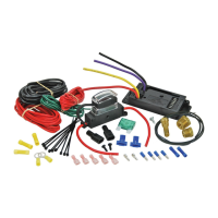
This document provides installation and wiring instructions for the Flex-a-lite Quick Start Motor Control Kit, models #31173 and #31174. This kit is designed to control electric cooling fans, integrating with the vehicle's electrical system and temperature sensing.

Function Description:

The Flex-a-lite Quick Start Motor Control Kit is an electronic control unit designed to manage the operation of electric cooling fans in a vehicle. Its primary function is to activate and deactivate the fans based on engine temperature and/or air conditioning (A/C) system demand. The controller ensures that the engine maintains an optimal operating temperature and provides additional cooling when the A/C is engaged. It features a quick-start capability, delaying fan activation during engine startup to prevent power draw interference. The unit includes diagnostic LEDs to indicate various operating conditions such as fan output, override conditions, A/C signal, and ignition signal.

Important Technical Specifications:

  • Mandatory Connections: The kit requires specific mandatory connections for proper operation: Battery Negative (BLACK), Negative to Fan (PURPLE), Positive to Fan (YELLOW), Battery Positive (RED), and Ignition Positive Signal. Temp Sensor Wires are also mandatory for temperature-based control.
  • Input Signals:
    • Battery Negative (BLACK): Connects to the vehicle's negative battery terminal.
    • Negative to Fan (PURPLE): Connects to the negative terminal of the fan motor.
    • Positive to Fan (YELLOW): Connects to the positive terminal of the fan motor.
    • Battery Positive (RED): Connects to the vehicle's positive battery terminal.
    • A/C Compressor Positive Signal (WHITE): Optional connection to the A/C compressor's positive signal wire. This allows the fans to engage when the A/C is on.
    • A/C Compressor Negative Signal (BROWN): Optional connection to the A/C compressor's negative signal wire. Only connect either the positive or negative A/C signal, not both.
    • Ignition Positive Signal (ORANGE): Connects to a switched 12-volt ignition source. This signal enables the controller and fans.
    • Temp Sensor Wires (GREEN): Two wires connect to the temperature probe, which is installed near the inlet hose.
    • Override Signals:
      • Negative Override Signal OFF (GRAY): Allows for external control to turn the fans off.
      • Negative Override Signal ON (BLUE): Allows for external control to turn the fans on.
  • Output Indicators (LEDs):
    • L1 (Fan Output Indicator): Illuminates when the fans are active.
    • L2 (Override Condition Indicator): Illuminates when an override signal is active.
    • L3 (A/C Signal Indicator): Illuminates when an A/C signal is detected.
    • L4 (Ignition Signal Indicator): Illuminates when the ignition signal is detected (after a 6-second delay).
  • Temperature Adjustment: The unit features a temperature adjustment screw. The total movement of this screw is approximately 3/4 of a turn. Turning the screw counterclockwise results in a cooler operating temperature, while turning it clockwise results in a warmer operating temperature. Exceeding the 3/4 turn limit can damage the unit.
  • Power Requirements: The system operates on a 12-volt electrical system. It is crucial that the vehicle's batteries and charging system are operating correctly to prevent improper fan or controller function.
  • Temperature Probe Installation: The temperature probe should be installed near the inlet hose, with approximately 1/4 inch of the probe protruding from the core. When crimping the temp probe wires, strip back the insulation and fold the wire back on itself to double the thickness for a secure connection.
  • Optional Manual Switch: The kit supports an optional Flex-a-lite Manual Switch (Part #31148) for manual fan control.

Usage Features:

  • Quick Start Delay: Upon ignition, there is a 6-second delay before the controller becomes fully active (indicated by LED L4 lighting up). This delay allows the engine to start without the fans drawing power, reducing strain on the battery and starter.
  • A/C Integration: The controller can be wired to detect when the A/C compressor is engaged. When the A/C is on, the fans will cycle with the A/C clutch, ensuring adequate cooling for the condenser and engine. LEDs L1, L3, and L4 will be lit when the fans are running under A/C demand.
  • Temperature-Based Control: The primary method of fan control is based on engine temperature, sensed by the included temperature probe. Users can adjust the desired operating temperature using the adjustment screw on the control unit.
  • Diagnostic LEDs: The four LEDs (L1-L4) provide visual feedback on the controller's status, aiding in troubleshooting and verification of proper operation.
  • Override Capability: The controller supports external override signals, allowing for manual activation or deactivation of the fans if desired.
  • Installation Guidance: The manual emphasizes the use of a quality crimping tool for wire connections, explicitly warning against the use of pliers or other devices to prevent damage.

Maintenance Features:

  • Pre-Installation Check: Before installation, it is recommended to ensure that the vehicle's batteries and charging system are in good working order. This helps prevent improper fan or controller function.
  • Temperature Adjustment: The temperature adjustment screw allows for fine-tuning of the fan activation temperature. This can be adjusted to maintain the desired engine temperature, which may vary based on vehicle usage or environmental conditions.
  • Electrical Surge Warning: A critical maintenance note advises disconnecting the VSC (Voltage Sensitive Controller) when charging the vehicle's battery or jump-starting the vehicle from an exterior source. Power surges from these activities can damage the VSC. It is recommended to disconnect both positive and negative leads to the controller prior to jump starting or charging the vehicle's electrical system to protect the unit.
  • Troubleshooting with LEDs: The diagnostic LEDs (L1-L4) are valuable tools for troubleshooting. For example, if fans do not turn on with the A/C, checking LED L3 can confirm if the A/C signal is being received by the controller. If LED L4 does not light up after 6 seconds of ignition, it indicates an issue with the ignition signal or power to terminal #9.

Flex-a-Lite 31173 Specifications

General IconGeneral
BrandFlex-a-Lite
Model31173
CategoryAutomobile Accessories
LanguageEnglish