In Step 1 you will make all the physical
connections required for basic HF/6m
operation of the FLEX-1500.
Back Panel
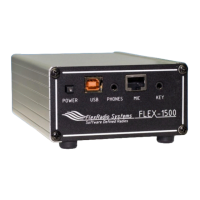
A: Ground
Connect the terminal marked GND to your
central station ground. NOTE: Make your
GROUND connection FIRST!
B: Antenna
Connect an HF antenna with a 50 Ohm
impedance or a dummy load to the BNC
antenna port marked ANTENNA.
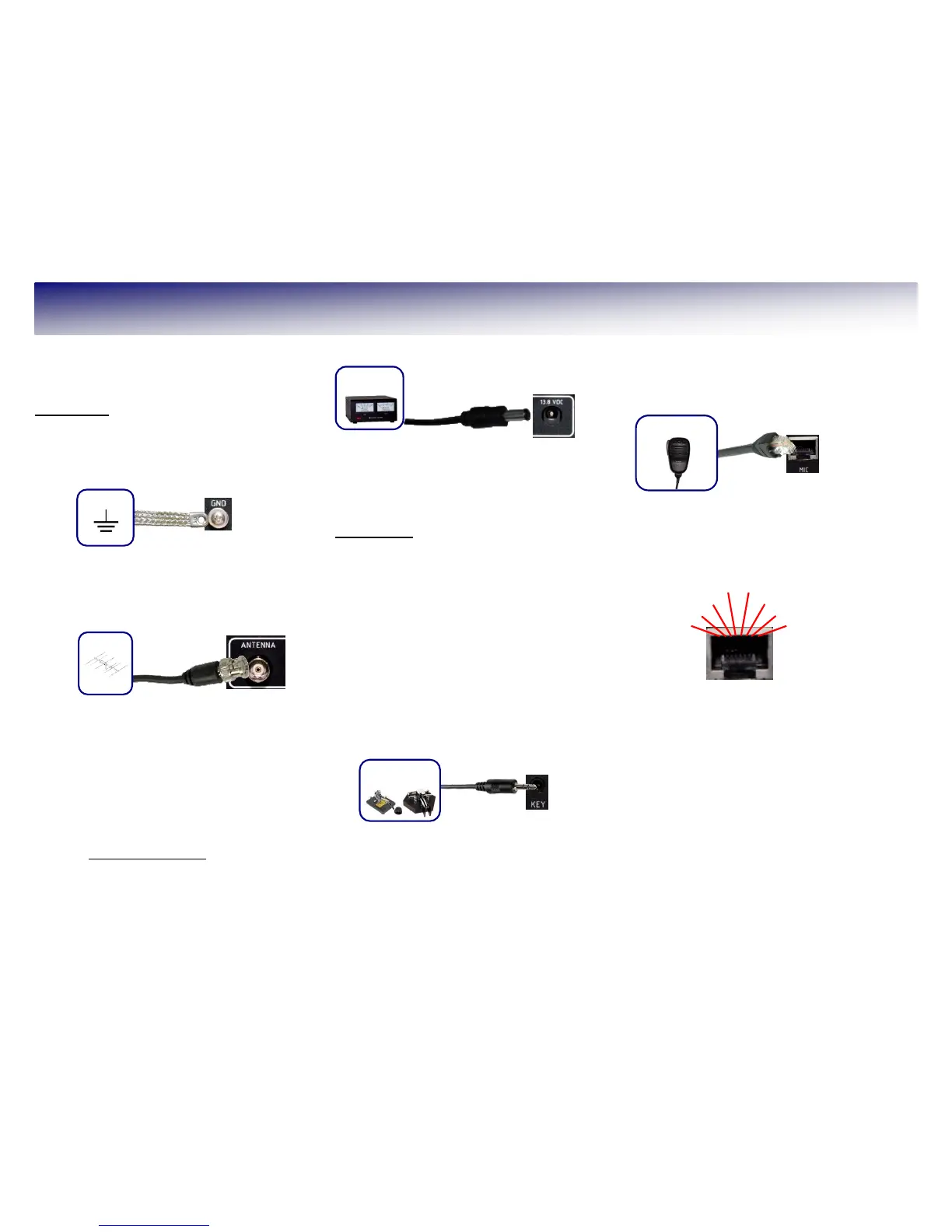
C: Power Supply - Do Not Power up the
FLEX-1500 at this time.
Use the power supply cable that came with
your FLEX-1500 to hook up a stabilized 13.8V
DC power supply to the jack marked 13.8
VDC. The power supply must be rated for 1.5A
continuous duty, 2A max. The power cable is
un-terminated at one end to allow you to
attach your own connector(s) if needed. Make
sure the wire with the stripe goes to the
positive and the solid color wire to the negative
terminal of your power supply. The polarity of
the power connector is wired so that the center
pin is positive (+) and the outer connector
jacket is negative (-).
NOTE: If your power source is not
current limited, you must add a 5 amp
fuse (not included) to the power supply
cable.
Front Panel
D: Paddles/Keyer/Key
Connect your CW paddles, keyer or straight
key to the jack marked KEY using a 1/8”
stereo (TRS) plug.
For paddles or a keyer, connect the Tip to
DOT, Ring to DASH and Sleeve to common.
For a straight key, connect Tip to KEY and
Sleeve to common. Do not connect the Ring.
The PowerSDR Keyer is configured for iambic
paddles by default. To change this, please see
the FLEX-1500 Owner's Manual.
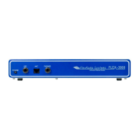
E: Microphone/PTT
Connect your microphone/PTT to the RJ-45
MIC jack.
The pin-out of the microphone jack is shown
below: