EasyManua.ls Logo

Flextherm LS240P User Manual

Flextherm LS240P
2 pages
To Next Page IconTo Next Page
Page #1 background imageLoading...
Page #1 background image
SUMMARY
OPTIONS SELECTION
On the back of the thermostat, there are 3 selection switches to set at
your preferences.
Temperature in °C or °F, time in 12 or 24 hours and Early Start function.
TO SET TIME AND DAY
Press on DAY, HOUR and MIN buttons to adjust time and day.
TO RECORD THE (COMFORT) SETPOINT TEMPERATURE
Select chosen setpoint temperature by using or button. Press on
button (2 to 3 seconds) until icon appears on display.
TO RECORD THE (ECONOMY) SETPOINT TEMPERATURE
Select chosen setpoint temperature by using or button.
Press on button (2 to 3 seconds) until icon appears on display .
CHECKING GROUND FAULT CIRCUIT INTERRUPTER (GFCI)
Adjust the setpoint temperature until heating indicator ( ) appears on
display. Press on TEST button. The test is conclusive if the warning light
(GFI) on thermostat is ON and power to the load is cut-off ( remain
on display though). If these events do not occur, check the installation.
Press on RESET button to reset the GFCI.
OPERATING MODES
To select an operating mode, use MODE button.
AUTO: Runs the program. or shows temperature setting
and can override temporarily your programming up to the
next program
MAN: Maintains the selected temperature. or changes
the temperature setting.
Power-up
When power is applied for the first time, the
display must show the time 00:00, the floor
temperature and the manual mode icon ( ).
Other information might show up on the display if
installation is defective or does not comply with
the instructions. The warning light (GFI) must be
off.
The message L0 or HI will appear on the display
if the temperature sensor is defective or the tem-
perature is below 0 °C (32 °F) or higher than
60 °C (140 °F). Also, the heating indicator will be
present on display and the relay will be closed
(current going in the load).
Checking ground fault circuit interrupter (GFCI)
Adjust the setpoint temperature until
heating indicator ( ) appears on
display. Press on TEST button. The test is
conclusive if the warning light (GFI) on the
thermostat is ON and power to the load is
cut-off. If these events do not occur, check
the installation. Press on RESET button to
reset the GFCI.
If the GFCI test fails:
Check the load wires. The thermost
at
must be in heating mode to carry out the
test (heating indicator ON).
The GFCI test should be carried out
monthly. If the test fails, cut off the electric
power to the heating system and call
customer service or return the thermostat
to your supplier for verification. If the
warning light comes on during normal
operation, cut off power to the heating
system and have an electrician verify the
installation.
LS240P
3840 W (NI) @ 240 VAC
LS24 0P
3840 W (NI) @ 240 VAC
INSTALLATION
This thermostat is designed to control floor electric heating systems. The
resistive load must not exceed 3840 watts (NI) @ 240 V
AC (16 A). The
thermostat is equipped with a ground fault circuit interrupter (GFCI) and therefore
the isolation of the line and load are required for operation. During a ground fault,
the two lines of the load will be cut off from the 240 V line. Connect thermostat as
shown on diagram.
This thermostat is an electrical product and must be inst
alled in conformity with
the national and/or local Electrical Code. The installation must be performed by
qualified personnel where required by law.
This thermostat is designed to be used with a heating system with circuit breaker.
PAR
TS INCLUDED
- One (1) LS240P (240 VAC) thermostat
- Two (2) 6-32 screws
- Four (4) solderless connectors (for copper wire)
- One (1)
Temperature sensor with a 15 foot extension
TURN OFF POWER OF THE HEATING SYSTEM AT THE MAIN POWER
PANEL TO
AVOID ELECTRICAL SHOCK.
Keep air vents of the thermostat clean
and free from obstructions.
1) Connecting wires and mounting thermostat
Connect the rear thermostat wires to the 240 V LINE and to the load using sol-
derless connectors for copper wires. See schematic diagram.
u
u
u
u
u
u
Push the excess wire back into the electrical box to prevent interference with
the thermostat. Secure the thermostat using two (2) 6-32 screws. Once the ther-
mostat is properly installed, return power to heating system.
NOTE: All cables and connections must conform to the local electrical code.
WARNING: Special CO/ALR solderless connectors must be used when
connecting with aluminum conductors.
2) Connecting temperature sensor wire
Connect the temperature sensor wire to the
two lower screws of the terminal block at
the back of the thermostat (no polarity need
to be respected). The wire must pass out-
side the electrical box and follow the wall
down to the floor. Install the sensor wire
between two runs of cable, at a distance of
30 to 60 cm (1 to 2 feet) within the heating
zone in a neutral location, away from any
source of heat or cold. Do not cross the
probe wire over the heating cable. Secure
the sensor to the floor with hot glue. It will
be necessary to recess the sensor in the
floor so it is at the same level as the heating
cable.
240 VAC
VAC
240
60 HZ
920-111-013-00-1-B LS240P0212A - Printed in China 1/2
OPERATING MODES
The LS240P has two (2) operating modes.
MANUAL ( )
This mode allows you to maintain a constant temperature of the floor.
1- To activate this mode, press on Mode button to display the icon.
2- Set the desired temperature using the buttons or select the
pre-programmed or or settings.
(To select the setting, press on and simultaneously.)
AUTOMATIC ( )
This mode executes your own programming.
To activate this mode, press on Mode button to display the icon.
The or icon indicates which temperature setting is used. Also, the icon
of the program number will be shown.
LS240P
Programmable Electronic
Thermostat (240 volt
s)
Question and Answer IconNeed help?

Do you have a question about the Flextherm LS240P and is the answer not in the manual?

Flextherm LS240P Specifications

General IconGeneral
DisplayLCD
Protection ClassIP20
ApplicationFloor Heating
Accuracy±0.5°C
MountingWall Mount

Summary

Summary and Options

Options Selection Switches

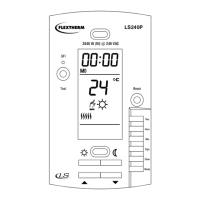
Explanation of the three selection switches for temperature, time, and early start function.

Setting Time and Day

Instructions on how to adjust the time and day using the DAY, HOUR, and MIN buttons.

Recording Comfort Temperature

Steps to select and record the desired comfort setpoint temperature.

Recording Economy Temperature

Steps to select and record the desired economy setpoint temperature.

GFCI Test Procedure

Guide on how to test the Ground Fault Circuit Interrupter for proper function.

Operating Modes Selection

How to select between AUTO and MAN operating modes using the MODE button.

Thermostat Wiring and Mounting

Wiring and Mounting Instructions

Instructions for connecting wires and physically mounting the thermostat.

Electrical Code Compliance

Emphasizes the need to follow local electrical codes for all connections.

Aluminum Conductor Warning

Crucial warning about using specific connectors for aluminum wiring.

Temperature Sensor Wire Connection

Sensor Wire Installation Details

Guidance on connecting the temperature sensor wire and its placement.

Initial Power-up Display

Power-up Behavior and Indicators

Describes the display behavior and indicators upon initial power application.

GFCI Testing Procedure

GFCI Test and Failure Diagnosis

Detailed steps to test GFCI, what to do if it fails, and troubleshooting advice.

General Installation Guidelines

Thermostat Installation Overview

Overview of thermostat installation for electric heating systems and load limits.

Electrical Code Installation Compliance

Mandates installation compliance with national and local electrical codes.

Circuit Breaker Compatibility

Notes that the thermostat is intended for use with a heating system that has a circuit breaker.

Included Parts List

Lists the components included with the LS240P thermostat package.

Electrical Shock Prevention

Critical safety instruction to turn off power before installation to prevent electric shock.

Thermostat Operating Modes

Manual and Automatic Modes

Explains the two operating modes: MANUAL and AUTOMATIC.

Manual Mode Operation

Details how to operate the thermostat in MANUAL mode for constant temperature.

Automatic Mode Operation

Explains how to operate the thermostat in AUTOMATIC mode for programmed schedules.

Memory and Time Backup

Power Failure Memory Retention

Describes how the thermostat retains programming and time during power failures.

Early Start Function

Early Start Functionality

Explains the Early Start feature that calculates optimal heating start times.

Programming Guide

Programming Time and Day

Steps to set the current time and day on the thermostat.

Programming Comfort, Economy, Vacation Settings

Instructions for setting desired temperatures for Comfort, Economy, and Vacation modes.

Schedule Programming Overview

Details on how to create custom heating schedules with 4 setting changes per day.

Example Comfort and Economy Schedule

Illustrates programming a typical daily schedule for comfort and economy periods.

Programming Saturday and Sunday Schedules

Specific instructions for modifying weekend schedules, including erasing programs.

Temporary or Permanent Temperature Bypass

How to temporarily override programmed settings or set a permanent vacation bypass.

Thermostat Characteristics

Product Specifications

Technical details including model, supply, load, power, GFCI class, and approvals.

Temperature Range Settings

Defines the display range, setting range, and default comfort/economy settings.

Product Warranty

One Year Limited Warranty

Details the terms and conditions of the one-year limited warranty for the thermostat.

Warranty Exclusions and Limitations

Outlines what is not covered by the warranty and liability limitations.

Returning Defective Merchandise

Instructions on how to return defective products to the retailer or installer.

Related product manuals