Document Title Document No. Revision
Date Section
Supplement S3 to the AMM CTLS-LSA –
CTLS-LSA with ROTAX 912iS
AF 0480 0011 00 05-Aug-12 75-00-2
Approval Ref.: Approved on the Basis of Manufacturer Self Declaration
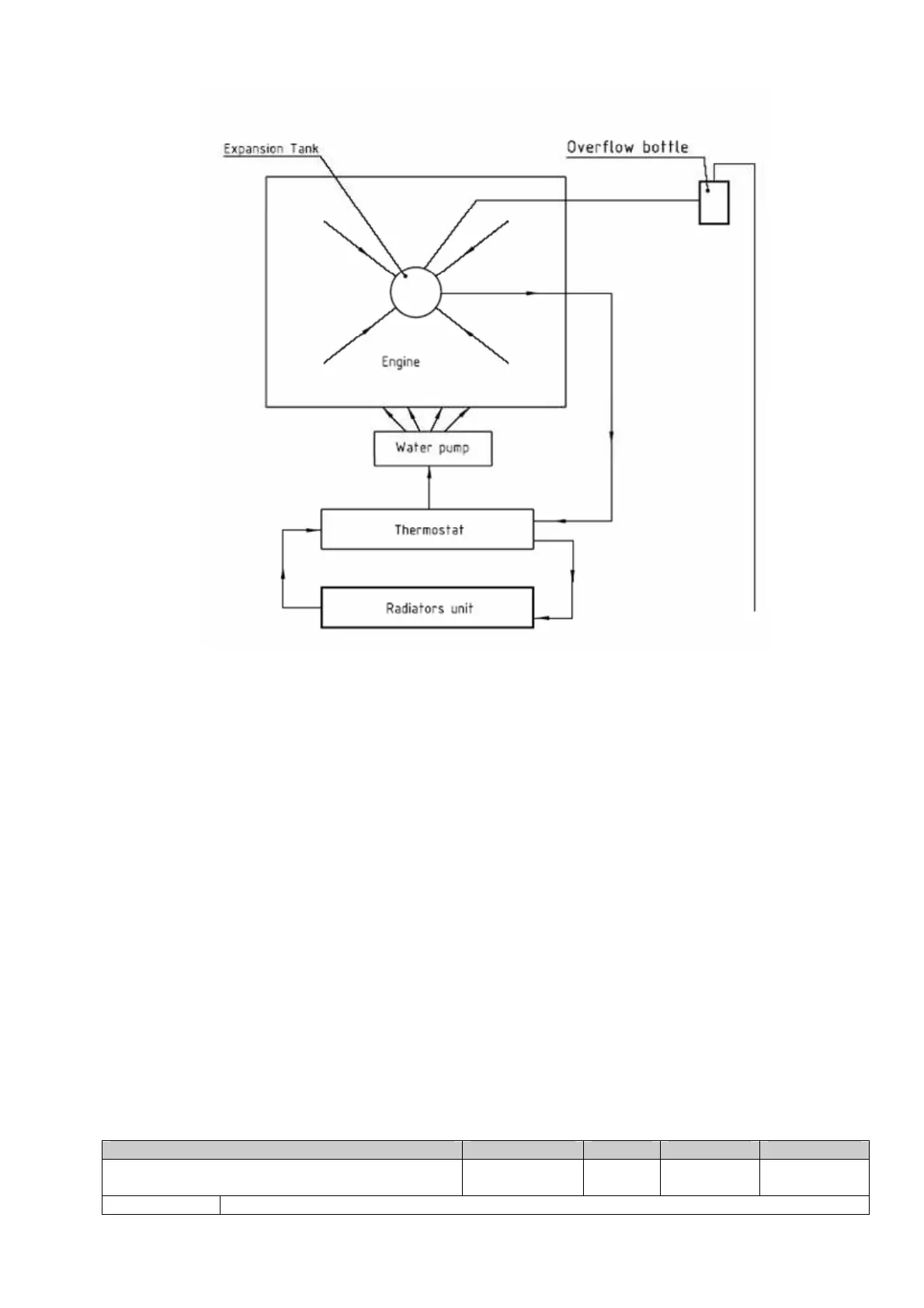
Fig. 75-00-2. Cooling system diagram with thermostat
From the top of the cylinder heads the coolant passes on to the expansion tank. Since the
standard location of the radiator is below engine level, the expansion tank located on top
of the engine allows for coolant expansion. The expansion tank is closed by a pressure
cap (with excess pressure valve and return valve). As the temperature of the coolant rises,
the excess pressure valve opens and the coolant will flow via a hose at atmospheric
pressure to the transparent overflow bottle. When cooling down, the coolant will be sucked
back into the cooling circuit. The overflow bottle is attached to the airframe structure. For
cooling system employed components (radiator, extension tank, overflow bottle,
thermostat (if use) and the set of connection fittings) supply together with engine by engine
manufacturer. Engine manufacturer provided all requirements to cooling system parts.
Cylinder head temperatures are measured by means of temperature probes installed in
cylinder heads.
Air cooling of cylinders provided by a composite cooling shroud is installed on the top of
crankcase. It directs fresh air from cowling air inlet to all cylinders.
 Loading...