Flint & Walling © Copyright 2018. All rights reserved.
5
Figure 3 Wire Illustration
NOTE: DO NOT USE ALUMINUM WIRE.
Attention: To meet full compliance with FCC Part 15
Subpart B and CENELEC EN 55011, shielded motor
cable should be used between the drive motor output and
the motor. Using shielded cable provides the maximum
filtering to reduce radiated & conductive emissions which
can cause interference with other devices.
CONTROLLER INSTALLATION PROCEDURE
1. Disconnect electrical power at the main breaker
2. Drain the system (if applicable)
3. Install pressure switch or transducer - the pressure switch
or transducer has a 1/4 - 18 National Pipe Thread (NPT)
connection.
4. Remove the controller cover by removing the lid screws.
Attach the unit to the wall using mounting screws (not
included).
Wiring Connections
1. Verify that the power has been shut off at the main
breaker.
2. Verify that the dedicated branch circuit for the controller is
equipped with the correct rating of circuit breaker.
3. Remove the controller lid.
L1
L2
IN OUT + - S1 S2
ALARMS FAN SENSOR
IL1791
RED
BLK
YEL
Feed motor and ground leads
through appropriate knockout
and connect to RED, BLK, YEL
and W on right hand terminal
block.
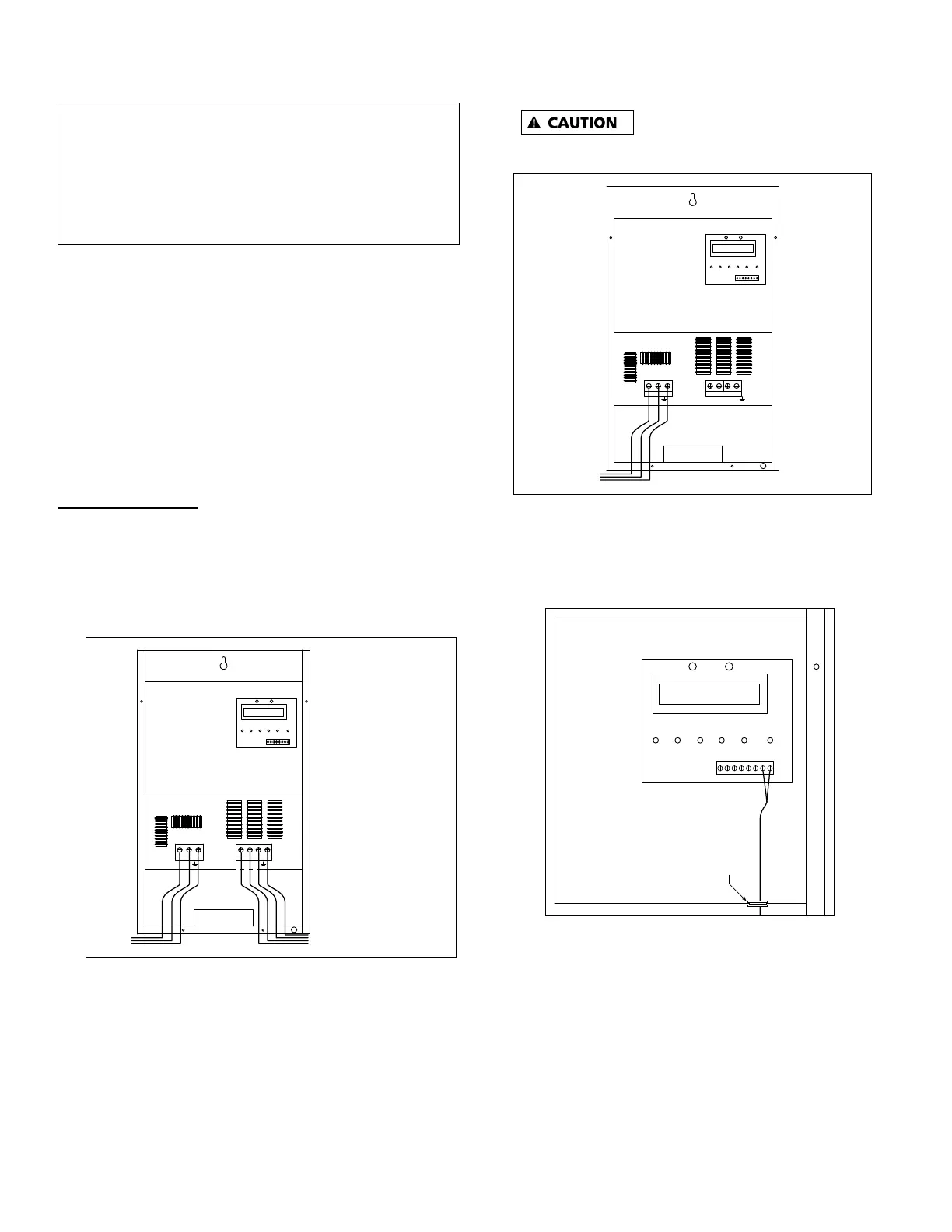
Figure 4
4. Feed the motor and ground leads thought the appropriate
knockout on the bottom right side of the unit and connect
them to the terminal block positions. Submersible
3-Phase or 3-Wire 1-Ph motors: follow colors as marked:
Red (RED), Black (BLK), Yellow (YEL) and (W).
Submersible 3-Phase or 3-Wire 1-Ph motors: follow
colors as marked: Red to RED, Black to BLK, Yellow
(YEL) and Green Ground wire (W). Submersible 2-Wire
1-Ph motors: Connect motor leads to BLK, YEL and
Green Ground wire (W).
Above Ground Motor (3-Phase Only): L1 to RED,
L2 to BLK, L3 to YEL and Green Ground wire (W)
Verify motor rotation to avoid damage
to pump & motor.
L1
L2
RED
BLK
YEL
IN OUT + - S1 S2
ALARMS FAN SENSOR
IL1790
Feed 230V power and ground
leads through appropriate
knockout and connect to
L1, L2 and W on left hand
terminal block
Figure 5
5. Feed the 230V power and ground leads through the
appropriate opening on the bottom left side of the
controller and connect them to the terminals marked L1,
L2 and W.
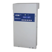
S2
IL1792
S1
Feed the pressure
switch/transducer
wire through the strain
relief (bottom right) and
route cable through
grommeted hole above
the motor power terminal
block.
Connect to S1 and S2
terminals on display board
terminal strip.
For transducer,
Brown wire connects to S1
Blue wire connects to S2
Grommeted hole
IN OUT + -
ALARMS FAN SENSOR
Figure 6
6. Install provided strain relief in the smaller hole on the
bottom right hand side of the controller unit. Feed the
pressure switch or transducer leads through the strain
relief and route the leads through the grommetted hole
above the motor terminals.
- For Switch (VS Drive Kit): Connect the red and black
lead wires to the terminals marked "S1" and "S2"
(interchangeable) on the display board terminal strip with
a small screwdriver (provided).
- For Transducer (TVS Drive Kit): Connect the Brown wire
to the terminal marked "S1" the Blue Wire to terminal