Do you have a question about the Flipper ZERO and is the answer not in the manual?
Lists necessary tools like a PH0 screwdriver and plastic tweezers or opening pick for Flipper repair.
Instructions to power off the Flipper device before commencing any repair procedures.
Remove four screws and gently press the top cover's sides to detach the bottom cover.
Remove an additional two screws to detach the internal part of the Flipper from the top cover.
Carefully press the battery connector wires to check if it causes the Flipper to power on.
Use tweezers or a plastic pick to detach the battery cable from the main board's connector.
Insert the battery cable back and verify if the Flipper powers on and can charge.
Repeat steps 1-3 in reverse order to reassemble your Flipper device.
This document outlines a self-diagnosis and repair guide for a device, likely a portable electronic gadget, referred to as "Flipper." The guide focuses on troubleshooting battery-related issues and provides step-by-step instructions for disassembling, inspecting, and reassembling the device.
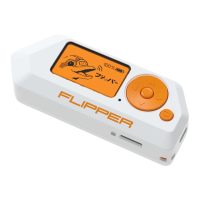
The Flipper device appears to be a compact, handheld electronic tool, possibly for various digital tasks given its display and button interface. The repair guide suggests it is powered by an internal battery, which is crucial for its operation. The device features a display screen, a directional pad (or similar control), and at least one additional button, indicating interactive functionality. The presence of an NFC/RFID module and a speaker is also noted on the internal circuit board, suggesting capabilities related to near-field communication, radio-frequency identification, and audio output. Furthermore, the device seems to support external storage via an SD card, as indicated by a message on its display during one of the diagnostic steps ("Need an SD card"). This implies the Flipper can store data, run applications, or perform functions that require additional memory.
The Flipper is designed for portability, as evidenced by its compact size and the need for an internal battery. Its user interface, comprising a screen and physical buttons, allows for direct interaction and control. The device's ability to power on, charge, and potentially interact with NFC/RFID technologies suggests a range of applications from data manipulation to security testing or even hobbyist projects. The modular design, where the internal components can be accessed and detached, points to a device that might be customizable or repairable by users with some technical aptitude. The guide implies that a properly functioning battery and its connection are fundamental for the device to operate, indicating that power management is a core aspect of its usage.
The provided guide is essentially a maintenance manual, detailing how to diagnose and potentially fix common power-related problems.
Overall, the Flipper is designed with a degree of user-serviceability, at least for common power-related issues. The detailed steps and visual aids (implied by the "Self diagnose and repair guide" title and the format of such guides) empower users to perform basic troubleshooting and repairs, extending the lifespan of the device and reducing the need for professional service for minor problems. The emphasis on careful handling and appropriate tools underscores the delicate nature of electronic components during maintenance.
| Microcontroller | STM32WB55 |
|---|---|
| Sub-GHz Transceiver | CC1101 |
| RFID | 125 kHz |
| NFC | 13.56 MHz |
| Infrared Transceiver | Yes |
| iButton | Yes |
| GPIO | Yes |
| Category | Hacking tool |
| Dimensions | 100 x 40 x 25 mm |
| Display | 1.4" LCD 128x64 |
| Bluetooth | Bluetooth 5.0 (LE) |
| Storage | MicroSD card slot |
| Power | USB-C |
| Battery | 2000 mAh LiPo |
| Connectivity | USB, Bluetooth |
| Weight | 102 g |
| Type | Portable multi-tool for pentesting |
| Compatibility | Multi-platform |