3 EN-US English
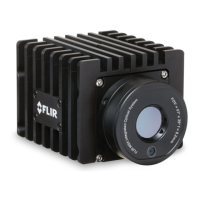
8. Infrared sensor.
9. Visual camera.
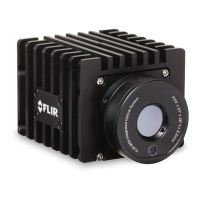
3.9 Cooling plate
See Figure 2.3 Mounting of camera on cooling plate, page 3.
The camera generates a considerable amount of heat during operation, which is
normal. To transfer this heat, it is recommended to mount the camera on the in-
cluded cooling plate.
3.10 Example system overviews
3.10.1 Early fire detection
Hot spot detection, self-combustible material on conveyor belt, see Figure 2.4
Example system overview: Early fire detection, page 4.
1. Coal mine conveyor belt.
2. FLIR A50/A70 Smart Sensor camera.
3. Ethernet connector, X-coded.
4. Power I/O connector, A-coded.
5. Digital output to a programmable logic controller (PLC).
6. Separate DIN rail power supply for galvanic isolation (18–56 V DC).
7. Laptop used for set up of the camera using the web interface.
8. Ethernet switch.
9. MQTT output connected to a third-party cloud service.
10. Example thermal image.
3.10.2 Condition monitoring
24/7 Monitoring of critical assets, see Figure 2.5 Example system overview: Con-
dition monitoring, page 4.
1. Computer running custom-made software.
2. CAT 6 Ethernet cable.
3. Industrial power over Ethernet (PoE) switch.
4. FLIR A50/A70 Image Streaming cameras.
5. Industrial process to be monitored, e.g., a gasifier.
6. Example thermal image.
#T810575; r. AB/75798/75798; mul 8
 Loading...