3 EN-US English
12. Import the images into FLIR Tools/Tools+ or FLIR Report Studio and create
an inspection report.
13. Send the inspection report to your client.
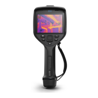
3.7 View from the front
See Figure 2.1 View from the front, page 3.
1. Laser distance meter.
2
2. Infrared lens.
3. Focus ring.
4. Autofocus button.
2
5. Trigger.
6. Lamp for the digital camera (left and right sides).
7. Digital camera.
8. Attachment point for the hand strap bracket (left and right sides).
9. Tripod mount.
10. Attachment point for the hand strap, wrist strap, or lanyard strap (left and
right sides).
3.8 View from the rear
See Figure 2.2 View from the rear, page 4.
1. Cover for the USB connector and memory card slot.
2. Microphone.
3. Speaker.
4. Touch-screen LCD.
5. Image archive button.
6. Programmable button.
7. Button to operate the laser.
8. Back button.
9. On/off button.
10. Navigation pad with center push.
11. Battery.
3.9 Screen elements
See Figure 2.3 Screen elements, page 5.
1. Result table.
#T810160; r. AH/47706/47706; mul 11
2. This item is dependent on the camera model.
 Loading...