910-0001-00-INS -R02 Page 34 of 53
Information contained in this document pertains to a Canadian origin product that is controlled as "dual use" by the Canadian government. However, when in
the United States or possessed by a US person, it may be considered a defense article from the US Government's perspective. US government authorization
may be required for re-transfer to a foreign person. If you have any questions, please contact FLIR's Global Trade Compliance group at
exportquestions@flir.com .
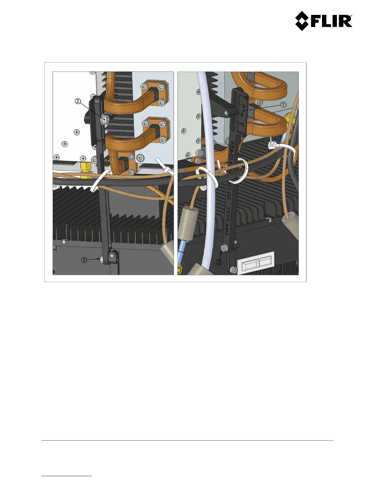
4.2.5 Antenna Tilt Adjustment Procedure — R1, R2, R3 and R3D
Figure 33 - Radar Antenna Tilt Adjustment – R1, R2, R3 and R3D
Step 1 Unfasten the 8 screws from under the base of the unit, then remove the radome
Step 2 Gently loosen screws (2) and (3), in Figure 4, until the antenna can be tilted
Step 3 Tilt the antenna to the desired angle, that is read on the Tilt angle indicator (1), then re-tighten
screw (3) to 10 in-lb and screw (2) to 22 in-lb, to maintain the antenna position
Step 4 Replace the radome and re-install the 8 screws at the bottom of the unit and tighten to 10 in-lb,
being careful not to overtighten. Hand-tighten only until resistance increases — base
seal should be
compressed by approximately 2 mm.
 Loading...