EasyManua.ls Logo

Flo SmartDC V3 - User Manual

Flo SmartDC V3
23 pages
Print Icon
To Next Page IconTo Next Page
Loading...
SmartDC
TM
V3
Installation Guide
Question and Answer IconNeed help?

Do you have a question about the Flo SmartDC V3 and is the answer not in the manual?

Summary

Specifications

Technical Specifications

Comprehensive technical details for 50 kW and 100 kW models, covering power, current, dimensions, and weight.

Integrated Protection

Details built-in safety features including surge, insulation, and continuity failure protection for reliable operation.

Standards Compliance

Lists adherence to key industry standards like UL, CSA, FCC, ensuring safety and regulatory alignment.

Dimensions

Center of Gravity

Exterior View of the Station

Interior View of the Station

Installation

Typical Installation

Illustrates a standard site layout with essential components like disconnect switches and parking spaces for optimal setup.

Site Preparation

Outlines critical site requirements: concrete slab, soil stability, drainage, and conduit placement for safe installation.

Safety Measures

Emphasizes ensuring the upstream disconnect is open and following workplace electrical safety procedures.

Installation of the Base on the Concrete Slab

Guides on aligning the station base with anchors and securely tightening bolts to the ground.

Installation of the Station on the Base

Details mounting the station to the base, including cable entry preparation and securing the unit.

Connecting the Charging Station

Provides instructions for preparing cable entry and connecting electrical conductors with specified torque values.

Installation of the Base Coverings

Explains the process of positioning and securing the side, front, and rear base cover plates for a finished look.

Cable Management System (Optional)

Describes the installation procedure for the optional cable management system counterweight.

Installing the Sign

Details how to align and fasten the top panel or sign onto the charging station.

Putting the Station into Service

Before Commissioning

Ensures electrical installation compliance, checks breaker status, and secures the enclosure before powering up.

Commissioning

Guides on post-power-up checks, server communication, and contacting support for final configuration.

Care and Maintenance of the Charging Station

Copyright and Liability

Overview

This document is the installation guide for the FLO SmartDC™ V3 charging station, a DC fast charging solution designed for electric vehicles.

Function Description:

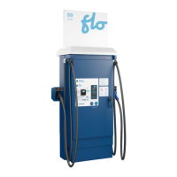
The FLO SmartDC™ V3 is an electric vehicle charging station that provides DC fast charging capabilities. It is designed to be installed on a concrete slab, either outdoors (Type 3R enclosure) or indoors, with specific ventilation requirements for indoor use. The station supports both SAE Combo (CCS1) and CHAdeMO output connectors, catering to a wide range of electric vehicles. It integrates various protection mechanisms, including against voltage surges, electrical insulation failures between DC output and ground, and continuity failures of the protective conductor (PE) between the charger and the vehicle. The station is equipped with a display, RFID card reader, and an optional credit card reader for user interaction. It also features a cable management system (optional) to keep the charging cables organized. The internal components include a door switch, a three-phase power supply terminal block with neutral, a grounding terminal, and AC/DC conversion modules.

Important Technical Specifications:

  • Type of charging station: DC fast charging station
  • Nominal power supply: Three-phase 480 Y/277 V
  • Nominal power:
    • 50 kW model: 54 kVA
    • 100 kW / 50 kW+ model: 108 kVA
  • Nominal current:
    • 50 kW model: 65 A
    • 100 kW / 50 kW+ model: 130 A
    • (Overcurrent protection must be selected according to local jurisdiction requirements)
  • Incoming terminals:
    • L1, L2, L3, Neutral terminal: (1) conductor size 4 AWG - 500 MCM (screw terminal)
    • Grounding terminal: (1) conductor size 14 AWG - 2/0 AWG (screw terminal)
  • Maximum output power:
    • 50 kW model: 50 kW
    • 100 kW / 50 kW+ model: 100 kW
  • Output connector: SAE Combo (CCS1) and CHAdeMO
  • Charging cables (maximum output current):
    • 50 kW model: 125 A
    • 100 kW / 50 kW+ model: 200 A
  • Charging cables (length):
    • Standard: 6.1 m (20')
    • Optional cable management system: 3.7 m (12')
  • Operating temperature range: -40 °C to 50 °C (-40 °F to 122 °F)
  • Storage temperature range: -40 °C to 70 °C (-40 °F to 158 °F)
  • Operating altitude: < 2000 m (< 6,562 feet)
  • Enclosure: Type 3R, for exterior use
  • Energy efficiency: Energy Star certified
  • Efficiency: 93% or better
  • Power factor: 98% or better
  • Weight:
    • Without cable management system: 255 kg (562 lb)
    • With cable management system: 300 kg (661 lb)
    • 100 kW / 50 kW+ model: 300 kg (661 lb)
  • Dimensions (with cable management system): 1,251 mm (49.25”) width. Without CMS: 1,232 mm (48.50”).
  • Center of Gravity (approx.): X: 25 mm (1''), Y: 940 mm (37''), Z: 58 mm (2'')
  • Standards Compliance: UL 2202, UL 2231-1, UL 2231-2, CSA C22.2 NO. 107.1-16, CSA C22.2 NO. 281.1-12, CSA C22.2 NO. 281.2-12, FCC part 15 Class A, ICES-3(A) / NMB-3(A).

Usage Features:

  • User Interface: The station features a display, an RFID card reader, and an optional credit card reader for payment and interaction. It also has a stop button and a start button.
  • Cable Management: An optional cable management system (CMS) is available, particularly for the 50 kW model, to help organize the charging cables.
  • Installation Flexibility: The product offers mounting configurations that support compliance with the Americans with Disabilities Act (ADA). Site design should be validated with local authorities.
  • Safety Features: Integrated protections against voltage surges, electrical insulation failures, and protective conductor continuity failures ensure safe operation. A master disconnect switch, visible from the charging station, is required for safety during installation and maintenance.
  • Indoor Installation Warning: For indoor installations, a sticker must be visible to the user stating: "WARNING: THIS UNIT IS DESIGNED ONLY FOR CHARGING VEHICLES THAT DO NOT REQUIRE VENTILATION WHILE CHARGING."
  • Power Supply: The station requires a three-phase 480 Y/277 V power supply. If a transformer is needed to match the available supply voltage, Y auto-transformers, Δ/Y transformers, or Y/Y transformers are acceptable. "Open Delta" auto-transformers or transformers with an "Open Delta" primary are prohibited.

Maintenance Features:

  • Regular Maintenance: The charging station requires regular maintenance to ensure proper operation and to maintain warranty validity. This maintenance must be performed by FLO qualified personnel.
  • Maintenance Tasks:
    1. Cleaning or replacing cooling system filters. Maintaining good airflow is crucial for cooling internal components.
    2. Inspection of critical components, such as connector cable assemblies and power conversion modules.
  • Maintenance Frequency: It is recommended to perform maintenance at least once a year or after 300 hours of use, whichever comes first. More frequent maintenance is advised if the station is installed in a dusty environment.
  • Technical Support: For installation issues or commissioning, FLO technical support can be contacted at 1 855 543 8356.

Flo SmartDC V3 Specifications

General IconGeneral
BrandFlo
ModelSmartDC V3
CategoryAutomobile Accessories
LanguageEnglish